How to Wire a UK 3-Pin Plug? Wiring a BS1363 Plug
Wiring a BS1363, 3-Pin Plug Safely and Correctly
What is a UK 3-Pin Plug?
A UK plug, also known as a British Plug, Type G Plug, or BS1363 Standard Plug by the International Electrotechnical Commission (IEC), is a three-pin plug used to power electrical appliances and devices. There are multiple types of three-pin plugs, such as Type A, B, C, D, E, F, G, H, I, J, K, L, etc. However, the G type 3-pin plug is most common in the United Kingdom, Singapore, Hong Kong, Malta, Malaysia, Ireland, Cyprus, Qatar, Oman, Kuwait, Saudi Arabia, the UAE, Israel, and other countries that fully or partially follow IEC regulations.
Related Posts:
- How to Wire a Twin 3-Pin Socket Outlet? Wiring 2-Gang Socket
- How to Wire a UK 3-Pin Socket Outlet? Wiring a BS1363 Socket
- Why Earth Pin is Thicker and Longer in a 3-Pin Plug?
Inside a 3-Pin Power Plug
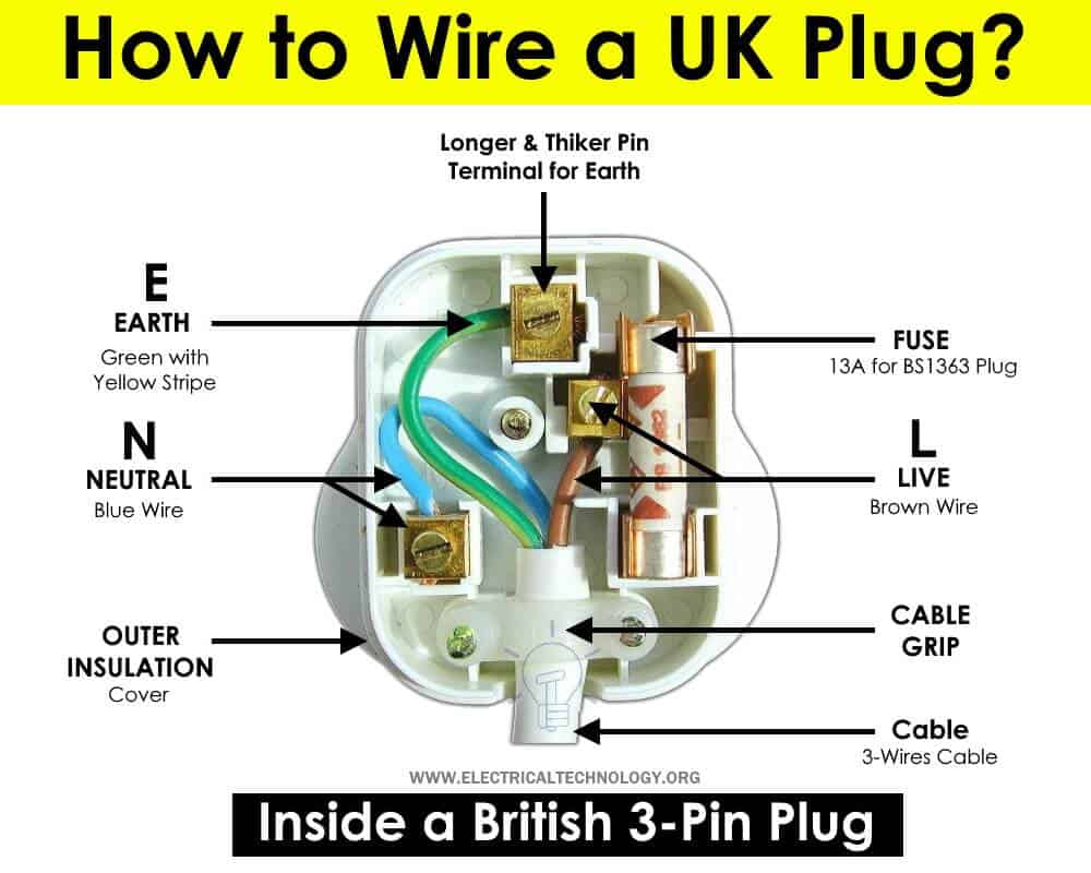
There are three terminals and a fuse inside a UK three-pin power plug, as follows:
Click image to enlarge

Live Terminal = L
The live terminal should be connected to the brown-colored wire (from the cable). It carries voltage and current from the source to the load point. The live terminal is also known as the hot, line, or phase terminal. The live terminal screw is electrically connected and bonded to the input of the safety fuse, while the output of the fuse is connected to the live pin.
Neutral Terminal = N
The Neutral terminal should be connected to the blue-colored wire. The Neutral wire provides a return path for the current when the circuit is completed.
Earth Terminal = E
The Earth terminal is longer and thicker for safety purposes. For this reason, the green with yellow stripe Earth wire should be connected to the Earth terminal.
Fuse
There is a built-in standard fuse (normally 13A) in a BS1363 plug. The rating of the ceramic fuse in the UK plug can be different, depending on the current capacity and types of protected loads. The main function of the fuse in a British plug is to protect the power cord, connected appliance, and cables and wires in case of overheating, overload, or overcurrent.
For example, a 13A fuse with 230V, 50Hz home supply voltage is equivalent to almost 3000 watts (3kW). If the load current exceeds the limit of the fuse rating (in the case of a fault, e.g., a short circuit), it will blow or trip the RCD/MCB circuit breaker in the main consumer unit.
Cable Grip
A cable grip is used to prevent tension on the cable during normal operation and to prevent the wire strands from pulling out of the screw terminals. The strain relief (cable grip) should be tightly fitted around the cable after connecting the wire strands to the appropriate terminals.
Related Posts:
- Single Phase Electrical Wiring Installation in Home – NEC & IEC
- Three Phase Electrical Wiring Installation in Home – NEC & IEC
Safety Features of BS1363 Plug
Good to know: The BS-1363 Plug, also known as the UK plug, is considered the safest plug in the world due to the following reasons:
- It has a built-in fuse.
- It has insulated pins.
- The earth pin is thicker and longer, ensuring it makes contact before other pins. The thickness of the pin prevents incorrect insertion into other slots, such as inserting Neutral into the Live or Earth into the Live terminal. In short, it cannot be inserted incorrectly.
- Shuttered outlets on sockets are used for 3-pin power plugs, preventing children from inserting nails or other conducting materials into the socket outlet. The longer earth pin helps to open the other two slots for Live and Neutral wires.
- The grip helps to remove the power plug easily.
- It can’t be used upside-down or in reverse to mix up the Live or Phase with Neutral.
Tools Needed
The following basic tools are required while wiring a 3-pin power plug.
- A 3-Pin UK plug
- Flat bladed screwdriver
- Phase tester
- Wire snips, side cutters, scissors, knife or simple wire striper.
Click image to enlarge
Related Posts:
- How to Wire 1-Phase Split Load Consumer Unit? – RCD+RCBO
- How to Wire 230V Dual Split Load Consumer Unit? – RCD+MCB
Wiring a UK 3-Pin Plug
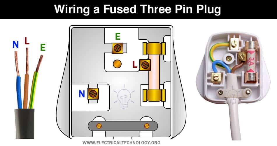
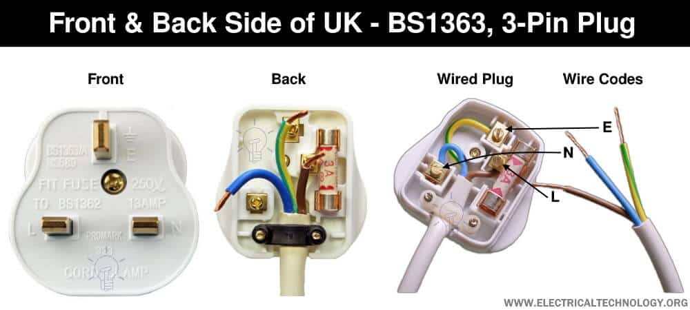
Follow these simple steps to wire a BS-1363 UK plug:
- Remove 2 inches or 5 centimeters of the outer sheath or insulation of the cable without damaging it, using a knife, snips, or wire stripper.
- Shorten the Live and Neutral (Brown & Blue) wires to a length that fits appropriately in the Live and Neutral screw terminals.
- Remove about half an inch (10mm) of insulation from the inner cores of all three wires (Brown, Blue, and Green/Yellow Stripe) using snips, a knife, or a wire stripper. Be careful not to damage the wire strands or conductors.
- It is a good practice to tightly twist all the wire strands and double them over before inserting them into the screw terminals. This helps avoid spreading the wire strands to other terminals and ensures the screws are tightened properly, especially for light gauge flex.
- Loosen the screws on the cable grip (strain relief) to easily connect the phase, neutral, and earth wire to the related screw terminals.
- Connect the Green with Yellow Stripe wire to the Earth “E” terminal.
- Feed the Blue wire into the Neutral “N” terminal.
- Finally, connect the Brown wire to the Live (Phase) “L” terminal.
- Tighten the cable grip (strain relief) screws and replace the back cover of the three-pin plug. Ensure all wires and screws are securely tightened to prevent hazardous fires due to arcing, overheating, or electric shock resulting in serious injuries.
Click image to enlarge
Related Posts:
- How to Wire a Three Phase, 400V Distribution Board? IEC & UK
- How to Wire Combo of 3 & 1-Φ, 400V/230V Distribution Board?
IEC & UK Wiring Color Codes: Old & New
IEC Wiring Color Codes for 230V, 1-Phase, 3-Wire System The Old UK wiring color codes for single phase wiring are as follow. 230V Single Phase
Related Posts:
Instruction & Safety Precautions
- Disconnect the main power supply (and ensure it is truly switched off) before servicing, repairing, or installing electrical equipment. To do this, turn off the main switch in the main consumer unit or distribution board.
- Never stand on or touch wet or metal parts while repairing or installing electrical equipment.
- Read all cautions and instructions carefully, and strictly follow them when completing this tutorial or any other practical work related to electrical tasks.
- Always use the right size cable and wire, proper size outlets and switch, and suitable size of circuit breakers. You may also use the Wire and Cable size calculator to find the right gauge size.
- Never attempt to work with electricity (as it is dangerous and can be fatal) without proper guidance and care. Perform installation and repair work in the presence of experienced individuals with vast knowledge and good practices who know how to deal with electricity.
- Doing your own electrical work is not only dangerous but also illegal in some cases. Contact a licensed electrician or the electric power supply provider before making any changes or modifications to electrical wiring connections.
- The distribution board should not be installed more than 2.2 meters above the floor, must be protected from corrosion, and kept away from watery areas. All wires should be covered inside the panel board (i.e., they should not hang outside the panel). Finally, there must be a safety sign near the distribution board.
- The author will not be liable for any losses, injuries, or damages resulting from the display or use of this information, or from attempting any circuit in the wrong format. Please be careful, as working with electricity is highly dangerous.
Related Wiring Installation Tutorials:
- How to Wire and Install an Electrical Outlet Receptacle?
- How to Wire a Garage Consumer Unit?
- How to Wire 240V, 208V & 120V, 1 & 3-Phase, High Leg Delta Main Panel?
- How to Wire 277V & 480V, 1-Phase & 3-Phase, Commercial Main Service Panel?
- How to wire a GFCI Outlet?
- How to Wire an AFCI Outlet?
- How to Wire Combo Switch and Outlet?
- How to Wire GFCI Combo Switch and Outlet
- How to Wire an AFCI Combo Switch
- How to Wire a GFCI Circuit Breaker?
- How to Wire an AFCI Breaker?
- Staircase Wiring Circuit Diagram – How to Control a Lamp from 2 Places?
- Corridor Wiring Circuit Diagram – Hallway Wiring using 2-Way Switches
- Tunnel Wiring Circuit Diagram for Light Control using Switches
- Hospital Wiring Circuit for Light Control using Switches
- Hotel Wiring Circuit – Bell Indicator Circuit for Hotelling
- Hostel Wiring Circuit Diagram and Working
- Godown Wiring Diagram – Tunnel Wiring Circuit and Working
- How to Wire 120V Water Heater Thermostat – Non-Simultaneous?
- Even More Electrical Wiring Installation & Tutorials


Thank you for step by step DIY guide.
The photo of the plug came from my guide here, so can you credit it please?
Hi Eugene Brennan,
The name of the author is already mentioned in the caption. Thanks