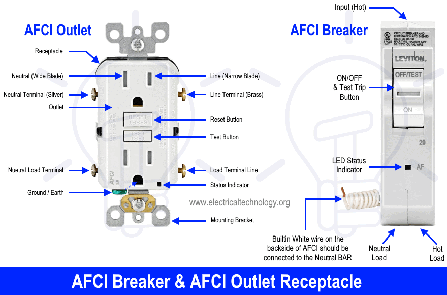
How to Wire an AFCI Breaker? Arc Fault Circuit Interrupter Wiring
Single Phase, Single Pole and Two Pole AFCI Breaker Wiring Installation
What is AFCI Breaker?
AFCI is the short version of “Arc Fault Circuit Interrupter” and also known as AFDD “Arc Fault Detector Device” or simply Arc Fault Breaker.
Arc Fault Circuit Interrupter (AFCI) is a protective device which detects the electric arc in the circuit and automatically break the circuit (cutoff power supply) to prevent electrical fire.
The ordinary circuit breaker won’t sense and operate that quickly during the initial stage of producing arc in the circuit. As these normal circuit breakers only respond to a specific amount of heat, not quick surges, that’s why AFCI are used to prevent the electric fire in the circuit.
The 2017 NEC (National Electrical Code) now requires the AFCI protection in almost all new construction such as bedrooms, living rooms, dining rooms, family rooms, kitchen, libraries, closets, libraries, laundry rooms, dens and other similar areas in a residential area. In short, All the single phase 120V, 15A and 20A branch circuits and outlet receptacles providing power supply must be protected by Arc Fault Circuit Interrupter breakers.
According to 2014 NEC, OBC (Outlet Branch Circuit) AFCI breaker or AFCI receptacle / outlet can be used to protect the circuit under various conduction. The OBC AFCI breaker and outlet will provide protection against both series (in single wire) and parallel (between two wires) arc. In addition, you may read the difference between GFCI and AFCI in the previous post.
Keep in mind that GFCI will not interfere with AFCI i.e. A ground fault circuit interrupter can be used and installed downstream to the arc fault circuit Interrupter. In Short, GFCIs can be wired with AFCIs in a circuit. In addition, GFCI protects against electric shock due to ground faults currents while AFCI protects against electrical fires in the circuits due to electric arcs.
Now, we will learn how to wire and install a single pole and two pole ground fault circuit interrupter circuit breakers in home.
Wiring a Single Pole AFCI Circuit Breaker
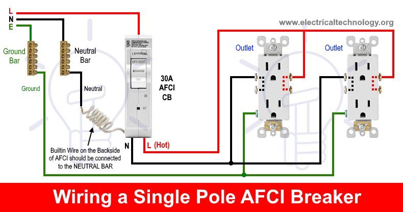
The following wiring shows two outlet receptacles has been wired and protected through single phase single pole AFCI circuit breaker.
As shown in the fig, the built in white wire on the back side of arc fault circuit interrupter circuit breaker has been directly connected to the neutral busbar in the main board. Keep in mind the AFCI wont work and protect the circuit if we don’t connected the white wire to the incoming neutral bar in the main distribution board.
The Line (Hot, Live or Phase) is directly connected to the AFCI input from main supply. The lower load terminals i.e. Hot and Neutral has been connected to the Line and Neutral terminals of both standard outlets. The ground wire is also connected from ground busbar to the receptacles ground terminals as shown in fig.
The illustrated wiring will protect the single phase 120V, 15 amperes outlets from arc faults by 30 amp AFCI circuit beaker. For 15 amp circuit, use 14 gauge wire while for 20 amp circuit, you may use 12# gauge wire size.
The same wiring can be done for 230V, 13A circuit using the correct wire size, proper circuit breaker rating and suitable rating of switches and outlets.
Special Notes:
- To avoid false tripping operation, do not install and wire an AFCI, GFCI, GFPE (Ground Fault Protection of Equipment) or Combo of both AFCI/GFCI circuit breakers on shared Neutral wire with other circuits.
- OBC AFCI (Outlet Branch Circuit Arc Fault Circuit Interrupter) can be used on all types of electrical wiring installation for both series and parallel arc quenching.
- It is not necessary to add AFCI protection devices on circuit extensions of less than 6′.
- A special device as combo of AFCI/GFCI can be used for both ground fault leakage currents and arc protection.
Related Post: How to wire a GFCI Outlet? – GFCI Wiring Circuit Diagrams
Wiring a Two Poles AFCI Circuit Breaker
The following wiring shows an electric stove, range or dryer has been wired and protected through a twp pole AFCI circuit breaker.
As there is no need of Neutral wire in 240V single phase supply but some 240V single phase appliances are needed to be wired with the neutral wire as well such as hot tub spa and dryer etc. The wiring should be followed by the manufacturer user manual guide and a licensed electrician.
In this four wire AFCI wiring diagram, two lines as L1 and L2 has been connected to the input terminals of AFCI breaker and the builtin white is connected to the neutral busbar in the mains supply.
The three load terminals of AFCI breaker is directly connected to the electric stove control box panel following the sequence as Line 1 (Red), Neutral (Black in the middle) and Line 2 (Blue). The ground / earth wire (as green) is connected to the ground terminal from ground busbar. This way, the connected device is AFCI protected.
General Precautions
- Switch off the main circuit breaker to make sure the power supply is OFF before wiring a GFCI outlet.
- Use the suitable voltage and ampere rating of switch with appropriate wire size and proper size MCB according to the load rating.
- Use the correct polarity i.e. verify the Load and Line terminals while installing a GFCI for protection. In other words, connect the wires to the correct side of outlet for proper operation.
- Regular maintenance, check and test is recommended while test the portable GFCI before each operation.
- Contact the authorized and licensed electrician for GFCI installation if you are not sure about the wiring diagrams.
- We have used Red for Hot or Line 1, Blue for Line 2, Black for Neutral and Green for Ground for illustration purpose only. Follow your own area wiring color codes according to NEC, IEC etc.
- The author will not be liable for any losses, injuries, or damages from the display or use of this information or if you try any circuit in wrong format. So please! Be careful because it’s all about electricity and electricity is too dangerous.
Related Wiring Installation Diagrams and Tutorials:
- Single Phase Electrical Wiring Installation in Home – NEC & IEC
- Three Phase Electrical Wiring Installation in Home – NEC & IEC
- How to Wire Auto &# Manual Changeover & Transfer Switch (1 & 3 Phase)
- Single-Phase Electrical Wiring installation in a Multi-Story Building
- Three-Phase Electrical Wiring installation in a Multi-Story Building
- How to Wire 120V Simultaneous Water Heater Thermostat?
- How to Wire 240V Water Heater Thermostat – Non-Continuous?
- How to Wire 3-Phase Simultaneous Water Heater Thermostat?
- Wiring of the Distribution Board with RCD (Residual Current Devices)
- Difference Between MCB, MCCB, ELCB & RCB (RCD or RCCB) Circuit Breakers
- Even More Electrical Wiring Installation & Tutorials


AFCI. & GFCI
WIRRING CONNECTION
Diagram