How to Wire GFCI Combo Switch and Outlet – GFCI Switch/Outlet Wiring Diagrams
GFCI Combo Switch and Outlet Wiring Circuit Diagrams and Installation
As discussed before, GFCI also known as ground fault circuit interrupter is a protection device against electric shock which detects the ground faults and leakage currents especially in outdoor and watery areas such as bathroom, kitchen, laundry etc.
Related Post: GFCI: Ground Fault Circuit Interrupter. Types, Working & Applications
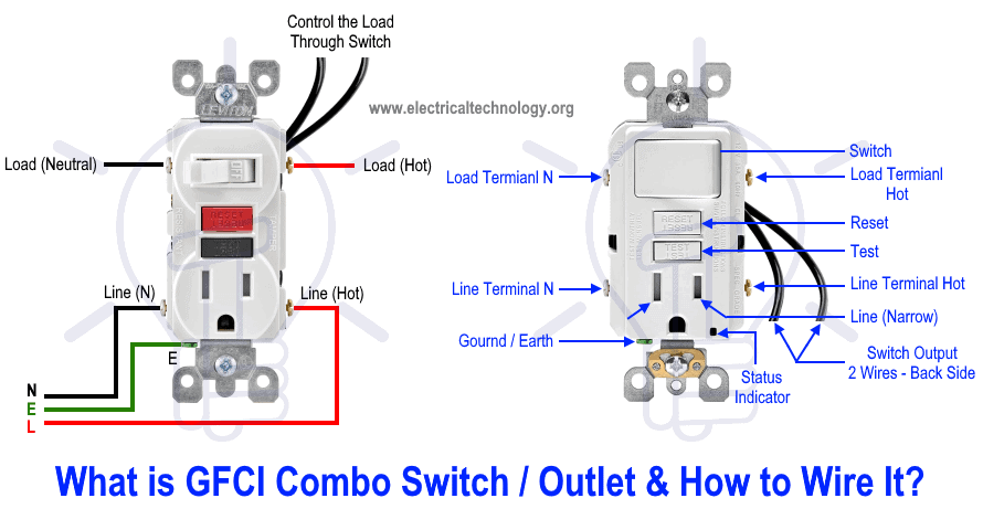
In our previous wiring tutorial, we have shown that how to wire a GFCI outlet with different protected and unprotected loads. The GFCI Outlet/Switch is different than the GFCI outlet as there are two outlet in a GFCI outlet and one outlet and one switch in the combo GFCI switch and outlet. There are additional two wires on the back side of GFCI Combo switch/outlet and we will show how to use them to control the different loads or GFCI combo itself.
For more details, see the NEC Code Requirements for GFCI.
What is GFCI Combo Switch/Outlet and How to Wire It?
Before installation, it is must to differentiate between a GFCI Combo Switch Outlet and ordinary Combo switch/ outlet . In both outlets, the Line (live, hot or phase) terminals are narrow blade while Neutral terminals has wide blades. In a GFCI outlet, there is no break away fin between the upper and lower terminals as like in normal combo outlet for line terminals. In normal combo switch-outlet, the line should be connected to the one Line terminal which is interconnected via break away fin i.e. both terminals are internally connected. The second i.e. wide blade of outlet should be connected to the neutral wire and load can be connected through the switch.
In today wiring tutorials, we will be showing how to wire and install a GFCI combo switch and outlet in residential areas to protect the light switch, ordinary outlet / receptacle, light and switches and use the switch in the GFCI combo to control the outlet in it. You may also read the basic difference between GFCI and AFCI in the previous post.
Related Post: How to wire a GFCI Outlet? – GFCI Wiring Circuit Diagrams
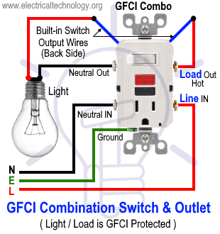
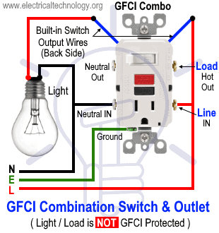
Wiring a GFCI Combo Switch Outlet with a Light bulb
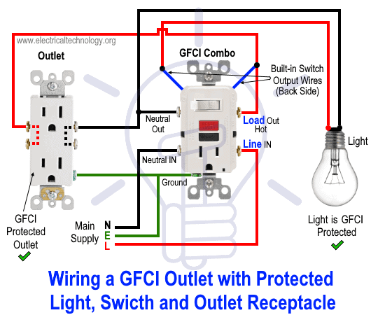
In the first wiring diagram, the connected load (as light bulb) is GFCI protected as it is control by the combo switch and connected to the load terminals of GFCI.
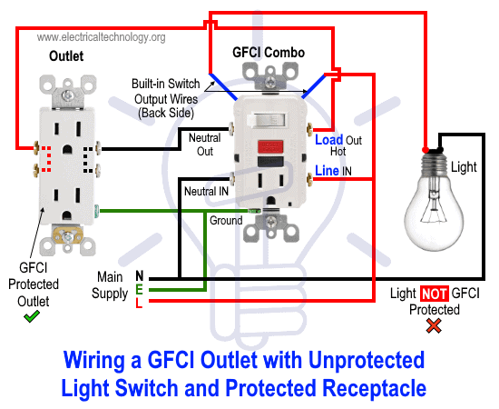
In the second wiring diagram, the lamp is connected directly to the line terminals of GFCI (i.e. direct main power supply). This way, the light can be control by the GFCI switch but it is not GFCI protected load.
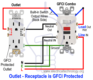
Wiring a GFCI Switch/Outlet with an Ordinary Outlet / Receptacle
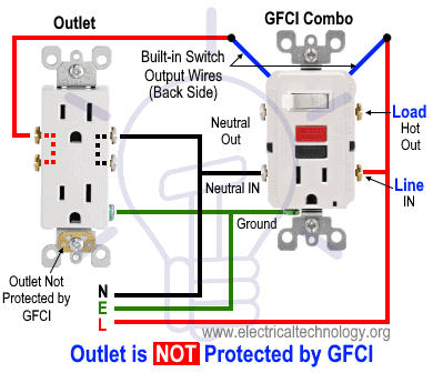
Same as the above wiring, the ordinary outlet / receptacle is GFCI protected and controlled by the switch as it has been connected the load terminals of GFCI.
In the following wiring diagram, the ordinary outlet is control by the GFCI switch but not GFCI protected as it has been connected and wired to the line terminals of GFCI.
- Related Post: How to Wire Combo Switch and Outlet?
Wiring a GFCI Combo Switch/Outlet with Protected Light & Outlet Receptacle
In this special case wiring diagram, Both light and ordinary outlet is connected to the load terminals of GFCI. The light ON/OFF operation can be controlled through the GFCI switch while the ordinary outlet is directly connected to the GFCI load terminals. This way, both loads i.e. light bulb and outlet and additional load connected to the ordinary load is GFCI protected.
In the following related wiring diagram, the ordinary outlet is connected to the load terminals of GFCI while the light bulb is connected to the line terminals of GFCI. This way, the ordinary outlet receptacle is GFCI protected while the light bulb is not GFCI protected.
Wiring a Switched GFCI Combo Outlet
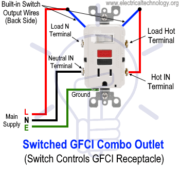
In this wiring tutorials, the switch in the GFCI combo switch – outlet has been controlled through the switch in it. In other words, the outlet in GFCI can be turn ON/OFF via upper switch in the GFCI combo.
To do this, simply connect the upper wire (there are two builtin wires on the back side of GFCI) to the line terminal of GFCI while the second wire should be wired to the incoming line (phase, live or hot) wire. Connect the ground / earth terminal to the ground wire from the main board. This way, the outlet in the GFCI can be controlled (ON/OFF operation) through the switch in the GFCI combo.
Precautions:
- Switch off the main circuit breaker to make sure the power supply is OFF before wiring a GFCI outlet.
- Use the suitable voltage and ampere rating of switch with appropriate wire size and proper size MCB according to the load rating.
- Use the correct polarity i.e. verify the Load and Line terminals while installing a GFCI for protection. In other words, connect the wires to the correct side of outlet for proper operation.
- Regular maintenance, check and test is recommended while test the portable GFCI before each operation.
- Contact the authorized and licensed electrician for GFCI installation if you are not sure about the wiring diagrams.
- We have used Red for Hot, Black for Neutral and Green for Ground for illustration only. Follow your own area wiring color codes according to NEC, IEC etc.
- The author will not be liable for any losses, injuries, or damages from the display or use of this information or if you try any circuit in wrong format. So please! Be careful because it’s all about electricity and electricity is too dangerous.
Related Wiring Tutorials:
- Corridor Wiring Circuit Diagram – Hallway Wiring using 2-Way Switches
- Tunnel Wiring Circuit Diagram for Light Control using Switches
- Hospital Wiring Circuit for Light Control using Switches
- Hotel Wiring Circuit – Bell Indicator Circuit for Hotelling
- Hostel Wiring Circuit Diagram and Working
- Godown Wiring Diagram – Tunnel Wiring Circuit and Working
- Even More Electrical Wiring Installation & Tutorials


Electrical and Electronics servicing Technology
I need reviews
Switch’s and more items are more important our electrical field
Why would you use such a weird color scheme for wiring diagrams? Why not match the wire colors to the already existing color code found In The real wires. This adds confusion to your content.