How to Wire a Single Element Water Heater and Thermostat?
Single Element Water Heater Thermostat Wiring Diagram
In the shivery and freezing to the bone season, we need hot water instead of her/him. If this is not the case for you (don’t tell a lie), I prefer speaking the truth “I Love Hot Water Too Much in the Cold and Snowy Weather”.
Well, we are not telling a love story here but want to show how to manage the hot water by wiring the hot water geyser and electric water heater wiring installation tutorial.
In this series, we will be showing how to wire different water heaters and thermostats like, single phase water heater, three phase water heater (balanced and unbalanced), continuous and non-continues (simultaneous and non-simultaneous) water heater installation, thermostats wiring diagram with switches and breaker rating.
In the first basic tutorial, we will be showing how to wire and install a single element water heater and thermostat for 120V AC single phase (US), 230V AC single phase (EU/UK) and 240V AC two lines US. Now let’s begin.
- Related Heater Wiring: How to Wire 120V Water Heater Thermostat – Non-Simultaneous?
Single Element Water Heater with Thermostat Wiring
A single element and one thermostat are generally used in smaller and point of use water heaters designed for single phase 120V or 230V AC.
The thermostat used in a single element electric water heater is different from the double (dual) element water heater. In other words, there are two screws on the right side in a single element thermostat switch which is fixed to the heating element while a dual element thermostat has 3 screws on the right side.
- Related Heater Wiring: How to Wire 120V Simultaneous Water Heater Thermostat?
Let’s see different wiring diagrams for single element water heater thermostats as follows.
120V AC Single Phase Single Element Water Heater Thermostat Wiring
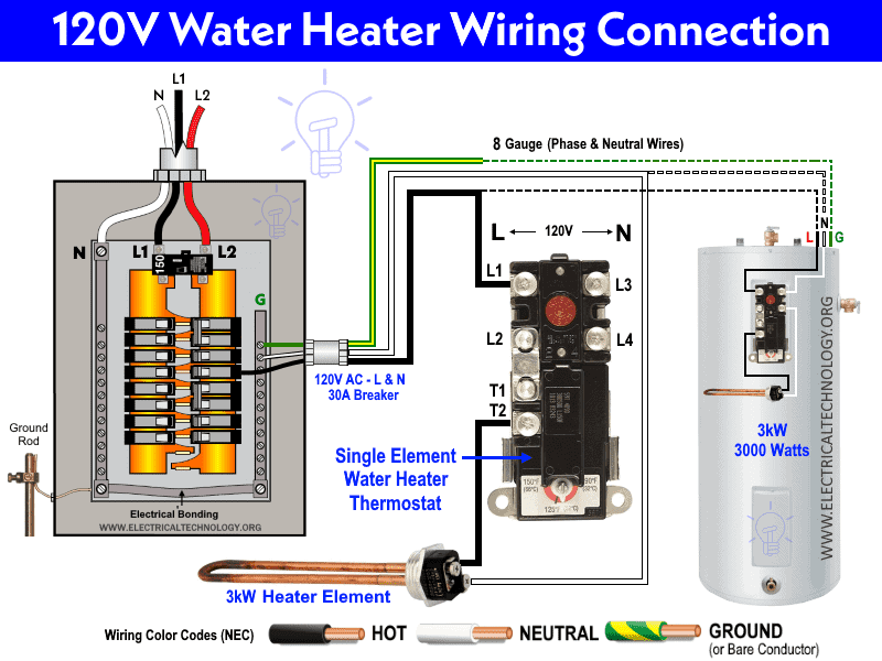
In this wiring connection, the phase line (L) from 120V/240V main panel (SP breaker) is connected to the L1 screw on the thermostat and then leaving the T2 terminal which is further connected to the single heating element. On the other hand, the neutral (N) is directly connected to the second terminal of the heating element. The earth or ground “G” is connected to the junction box of the water heater.
The rating of the water heater element is 3kW. Since the supply voltage is 120V, hence it draws the maximum of 25 amperes current (Ohm’s law: I = P/V). This way, a 30A circuit breaker and 8 gauge wire for both line and neutral is suitable according to the rating. The safe maximum current of the circuit breaker is 80% i.e. 30A x 0.8 = 24A. In other words, the circuit breaker should be rated about 125% of full load current i.e. 25A load current x 125% = 31.25 A. So the nearest 30A breaker can be used.
Click image to enlarge
240V & 120V AC Single Phase Single Element Thermostat Wiring Connection
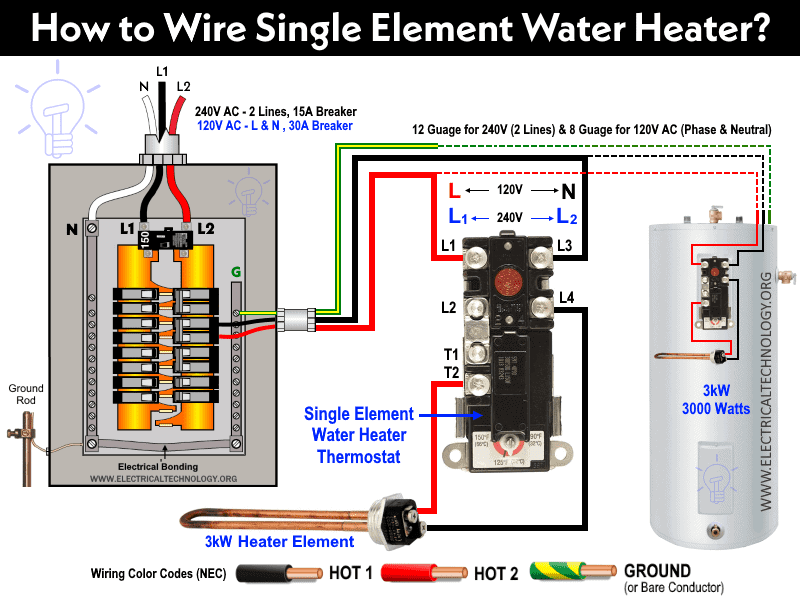
The same thermostat can be wired for both 120V AC (Line and Neutral) and 240V AC (two lines or phase wires). In the following water heater wiring diagram, a 3000 Watts single heating element is shown connected to 120V AC as well as 240V AC.
The wiring connections for both single phase 120V and 240V are the same i.e. the Line is connected to the L1 terminal while neutral or second line is connected to the L3 terminal. The water heater element is connected to the thermostat via T2 as hot and L4 as neutral. Black color is “Neutral” while red is “Phase or Line” and the yellow/green wire is used for ground / earth. The colors are used for showing the wiring connection purposes and it may vary according to the different areas and location. Please follow your own codes and regulations. For more details, see the footer note for wiring color codes and voltage levels of NEC and IEC.
In a 120V connection, the 3000 watts heating element draws 25A current, so 8 gauge wires for neutral and line have been used with a 30A breaker or fuse.
In 240V connection, the 3kW heater element draws 12.5A current, thus a 12 gauge wire for both lines and 15A over current protection circuit breakers can be used.
Click image to enlarge
230V, 240V & 120V AC Single Element Thermostat Wiring Diagram
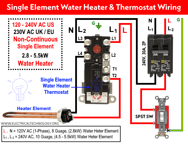
The following water heater diagram shows different connections i.e. single phase 120V AC and 240V two phases in USA (NEC) while single phase 230V AC in UK and EU (IEC).
In the first case, a 2.8kW single element water heater is connected to the 120V AC (Line and Neutral) which draws 23.33 amp current.
In case of 120V AC single phase (Line and Neutral), 8 gauge wires are used with a 30 amp circuit breaker and a single way (SPST = Single Pole Single Throw) switch having 30A rated current and the safe limit of current is 24A (30A x 80%). In other words, 23A x 1.25 = 28.75. The nearest rating is 30A breaker which is suitable to use in a 120V, 2800 Watts water heater.
In case of 240V AC (US) or 230V AC (EU / UK), a 5.5kW single element water heater is connected to the supply voltage through a 30A breaker and single way switch where the element circuit draws 22.91A in 240V two lines and 23.91A in 230V line and neutral.
The wiring connection is the same despite both wires connected to the L1 and L3 are two hot lines in case of 240V AC while the L1 is Hot and L3 is Neutral in case of 230V AC. For 22.91A or 23.91A, a 10 gauge wire is suitable with a 30A switch and protection circuit breaker as shown in the wiring diagram.
Click image to enlarge
Good to Know:
- A dual element thermostat can be used for a single element water heater.
- A single element thermostat can’t be used for a double element water heater.
- A single element thermostat can only be used for dual elements in case of simultaneous (continuous) operation of redundant elements which need different wiring connections (we will show in the next posts of this series).
- A 240V AC water heater element can be connected to the 120V AC.
- A 120V AC water heater element can’t be used for 240 or 230V.
- An upper thermostat of 240V can’t be used with a single element water heater as the single element thermostat looks similar to the upper thermostat of dual element thermostat. Care must be taken for replacing the appropriate thermostat.
- 30A Breaker and 10 gauge wire can be used on 240V AC water heater
- A switch rated for 15A, 120V can be used on 20A, 120V circuit.
- A switch rated for 20A, 120V can’t be used on household 15A, 120V circuits.
- A switch rated for 120V can’t be used on 240V circuits and vice versa.
- A 240V switch can be used on a 120V circuit if the ampere rating is the same.
- A 120V switch can’t be used on 240V circuit even if current rating in amperes are the same.
- An oversized breaker used for protection can damage the water heater or other connected appliances and even lead to the fire due to overheat.
- An oversized switch is OK but lower rating than the load current can melt the switch contacts.
- An undersized breaker or same rating with load current breaker can trip and reset the circuit again and again. Use the correct size breaker.
In addition, A switch rated for:
- 120V can only be used for 120V.
- 240V can be used for 120V, 240V but not for 277V (Commercial applications)
- 120-277 can be used for 120V, 240V and 277V.
Related Water Heater Wiring: How to Wire 240V Simultaneous Water Heater Thermostat?
Circuit Breaker Protection & Wire Gauge Size Chart For Water Heater
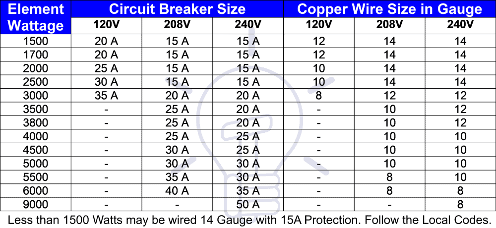
The following chart shows the circuit breaker size in amperes and copper wire size in gauge for 120V, 208V and 240V AC.
| Element Wattage | Circuit Breaker Size | Copper Wire Size in Gauge | ||||
| 120 V | 208 V | 240 V | 120V | 208 V | 240 V | |
| 1500 | 20 A | 15 A | 15 A | 12 | 14 | 14 |
| 1700 | 20 A | 15 A | 15 A | 12 | 14 | 14 |
| 2000 | 25 A | 15 A | 15 A | 10 | 14 | 14 |
| 2500 | 30 A | 15 A | 15 A | 10 | 14 | 14 |
| 3000 | 35 A | 20 A | 20 A | 8 | 12 | 12 |
| 3500 | – | 25 A | 20 A | – | 10 | 12 |
| 3800 | – | 25 A | 20 A | – | 10 | 12 |
| 4000 | – | 25 A | 25 A | – | 10 | 10 |
| 4500 | – | 30 A | 25 A | – | 10 | 10 |
| 5000 | – | 30 A | 30 A | – | 10 | 10 |
| 5500 | – | 35 A | 30 A | – | 8 | 10 |
| 6000 | – | 40 A | 35 A | – | 8 | 8 |
| 9000 | – | – | 50 A | – | – | 8 |
Less than 1500 Watts may be wired 14 Gauge with 15A Protection. Follow the local codes.
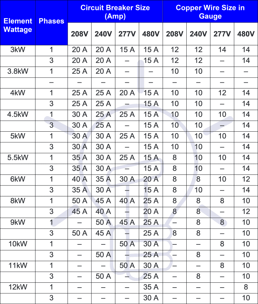
Below is the chart of circuit breaker or fuse over current protection in amperes and wire gauge size based on NEC Table 310-16 considering the temperature of 75Co for water heaters elements range from 3kW to 12kW for 208V, 240V, 277V and 480V AC.
| Element Wattage |
Phases |
Circuit Breaker Size (Amp) | Copper Wire Size in Gauge | ||||||
| 208V | 240V | 277V | 480V | 208V | 240V | 277V | 480V | ||
| 3kW | 1 | 20 A | 20 A | 15 A | 15 A | 12 | 12 | 14 | 14 |
| 3 | 20 A | 20 A | – | 15 A | 12 | 12 | – | 14 | |
| 3.8kW | 1 | 25 A | 20 A | – | – | 10 | 10 | – | – |
| – | – | – | – | – | – | – | – | – | |
| 4kW | 1 | 25 A | 25 A | 20 A | 15 A | 10 | 10 | 12 | 14 |
| 3 | 25 A | 25 A | – | 15 A | 10 | 10 | – | 14 | |
| 4.5kW | 1 | 30 A | 25 A | 25 A | 15 A | 10 | 10 | 10 | 14 |
| 3 | 30 A | 25 A | – | 15 A | 10 | 10 | – | 14 | |
| 5kW | 1 | 30 A | 30 A | 25 A | 15 A | 10 | 10 | 10 | 14 |
| 3 | 30 A | 30 A | – | 15 A | 10 | 10 | – | 14 | |
| 5.5kW | 1 | 35 A | 30 A | 25 A | 15 A | 8 | 10 | 10 | 14 |
| 3 | 35 A | 30 A | – | 15 A | 8 | 10 | – | 14 | |
| 6kW | 1 | 40 A | 35 A | 30 A | 20 A | 8 | 8 | 10 | 12 |
| 3 | 35 A | 30 A | – | 15 A | 8 | 10 | – | 14 | |
| 8kW | 1 | 50 A | 45 A | 40 A | 25 A | 8 | 8 | 8 | 10 |
| 3 | 45 A | 40 A | – | 20 A | 8 | 8 | – | 12 | |
| 9kW | 1 | – | 50 A | 45 A | 25 A | – | 8 | 8 | 10 |
| 3 | 50 A | 45 A | – | 25 A | 8 | 8 | – | 10 | |
| 10kW | 1 | – | – | 50 A | 30 A | – | – | 8 | 10 |
| 3 | – | 50 A | – | 25 A | – | 8 | – | 10 | |
| 11kW | 1 | – | – | 50 A | 30 A | – | – | 8 | 10 |
| 3 | – | 50 A | – | 25 A | – | 8 | – | 10 | |
| 12kW | 1 | – | – | – | 35 A | – | – | – | 8 |
| 3 | – | – | – | 30 A | – | – | – | 10 | |
Related Posts:
- How to Wire 3-Phase Simultaneous Water Heater Thermostat?
- How to Wire 3-Phase Non-Simultaneous Water Heater Thermostat?
IEC and NEC Wiring Color Codes
Wiring Color Code: The wiring color codes vary in different regions. You may use the specific area wiring color codes i.e. IEC – International Electrotechnical Commission (UK, EU etc) or NEC (National Electrical Code [US & Canada] where; NEC: Black = Phase or Line, White = Neutral and Green/Yellow = Earth Conductor Black = Phase 1 or Line 1, Red = Line 2, Blue = Line 3 & White / Gray = Neutral and Green/Yellow = Earth Conductor IEC: Brown = Phase or Line, Blue = Neutral and Green = Earth Conductor Grey= Phase 1 or Line 1, Black = Line 2, Brown = Line 3, Blue = Neutral and Green= Earth Conductor
The wire gauge and circuit breaker size for water heater charts are given below as a reference to download for later use.
Related Posts:
- How to Toggle Electric Water Heater Between 120V and 240V?
- How to Control Electric Water Heater using Switches?
General Precautions
- Electricity is our enemy, if you give it a chance to kill you, remember, they will never miss it. Please read all caution and instructions while doing this tutorial in practical.
- Don’t guess. Always disconnect the power source by switching off the main circuit breaker before servicing, repairing or installing electrical equipment.
- Use the suitable voltage and ampere rating of switch with appropriate wire size and proper size of breaker according to the load rating.
- Never try to work on electricity without proper guidance and care.
- Work with electricity only in presence of those persons who have good knowledge and practical work and experience who know how to deal with electricity.
- Read all the instructions and cautions and follow them strictly.
- Doing your own electrical work is dangerous as well as illegal in some areas. Contact the licensed electrician or the power supply company before practicing any change in electrical wiring connection.
- The author will not be liable for any losses, injuries, or damages from the display or use of this information or if you try any circuit in the wrong format. So please! Be careful because it’s all about electricity and electricity is too dangerous.
In this basic post, we discussed the single element electric water heater and thermostat wiring. In our next posts, we will be showing the simultaneous and non simultaneous, three phase water heater installation and how to control them. Also, let us know in the comment box below with valuable suggestions or if you need help with a specific wiring tutorial. Stay tuned and share with your friends.
Related Wiring Installation Tutorials
- How to Wire 120V & 240V Main Panel? Breaker Box Installation
- How to Determine the Number of Circuit Breakers in a Panel Board?
- How to Size a Load Center, Panelboards and Distribution Board?
- How to Determine the Right Size Capacity of a Subpanel?
- Single Phase Electrical Wiring Installation in Home – NEC & IEC
- Three Phase Electrical Wiring Installation in Home – NEC & IEC
- How to Wire Auto & Manual Changeover & Transfer Switch – (1 & 3 Phase)
- How to Connect a Portable Generator to the Home Supply – 4 Methods
- How to Wire Analog and IP PTZ Camera with DVR and NVR?
- How to Wire Different Fire Alarm Systems – Conventional & Addressable
- Even More Residential Wiring Installation Tutorials


Hello,
Thermostat went out on my Dual electric water heater. I have a working single element already on hand I can use. I’m needing to see the wiring diagram when using single element thermostat for dual element so I can change it.
Thank you
LIAM
I would like to install tankless water heaters in bathrooms and kitchen area, can you advise proper wiring guidance and balancing procedures for breaker box, Thank you, Jonathan Everdyke