How to Wire 120V & 240V Main Panel? Breaker Box Installation
Wiring Installation of Single Phase 120V & 240V Circuits & Breakers in Main Service Panel
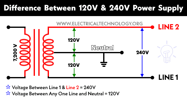
In the USA and Canada (following NEC and CNC), the distribution transformer has 4.5kV-7.2kV at primary side and step-down the voltage level to 120V single phase and split phase 240V for residential applications. The primary side of the distribution transformer is fed up by two lines named as high voltage line and neutral respectively.
The secondary winding is center tapped i.e. there are three outgoing wires from the secondary winding named as Hot 1 or line 1, Hot 2 or line 2 and Neutral. The voltage level between any hot “hot1 or hot 2” and neutral wire is 120V while the voltage between two hot wires “hot 1 and hot 2” is 240V. Both supply voltage levels are single phase supply system except two hot wires provide out of phase (180°) voltage as compared to 120V between hot and neutral.
These three wires enter to the meter box and then connect to the main panel box. In the following tutorial, we will show how to wire single phase 120V and 240V circuit breakers and load in the main panel box in home for residential purposes.
Related Post:
- How to Wire 208V & 120V, 1-Phase & 3-Phase Main Panel? Distribution Board Wiring
- How to Wire 240V, 208V & 120V, 1 & 3-Phase, High Leg Delta Main Panel?
Inside Main Breaker Box
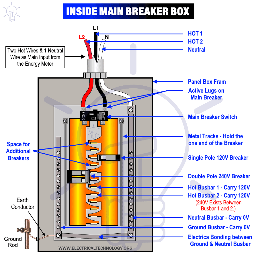
The following figure shows a typical breaker box panel for 120V and 240V circuits. There are three wires entering the main panel from the energy meter viz:
- Hot 1 or Line 1 = Black Color
- Hot 2 or Line 2 = Red Color (for illustration purpose only)
- Neutral = White Color
Click image to enlarge
Hot 1 and hot 2 wires are tightly connected to the lugs of the main circuit breaker (main switch). Keep in mind that these lugs are always active no matter if the main breaker switch is ON or OFF.
The main breaker is connected to the two busbars (For illustration purpose, Black and red color are used for these two busbars). Busbar 1 and busbar 2 carries 120V and there are 240V between two busbars (i.e. hot1 and hot 2).
The white neutral is connected to the neutral busbar which carries 0V. Additionally, the neutral busbar is bonded to the ground busbar for safety purposes which also carries 0V. Keep in mind that all the metal boxes should be properly earthed and ground according to NEC rules.
This way,
- Voltage between Hot 1 and Neutral = 120V Single Phase
- Voltage between Hot 1 and Hot 2 = 240V Single Phase (Split phase voltage)
- Voltage between Neutral and Ground = 0V.
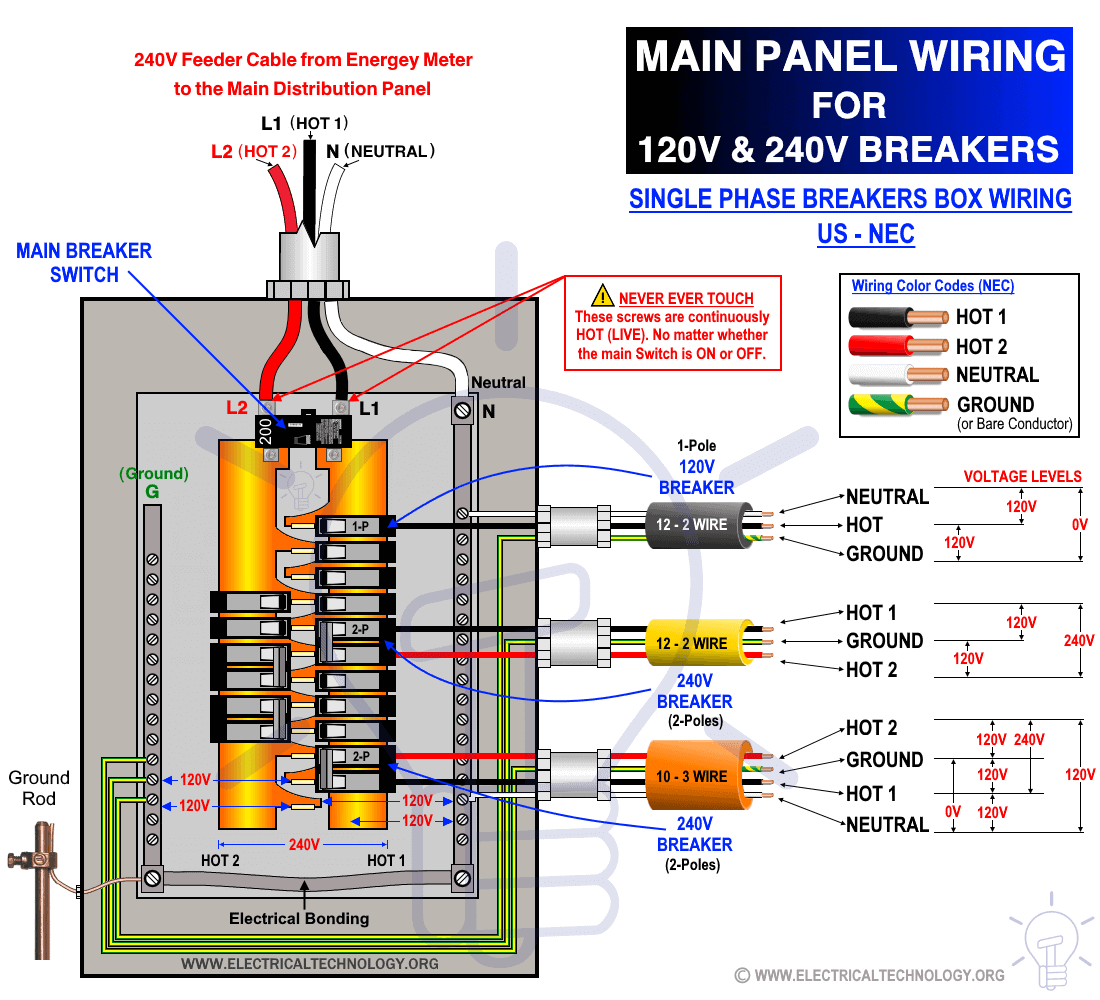
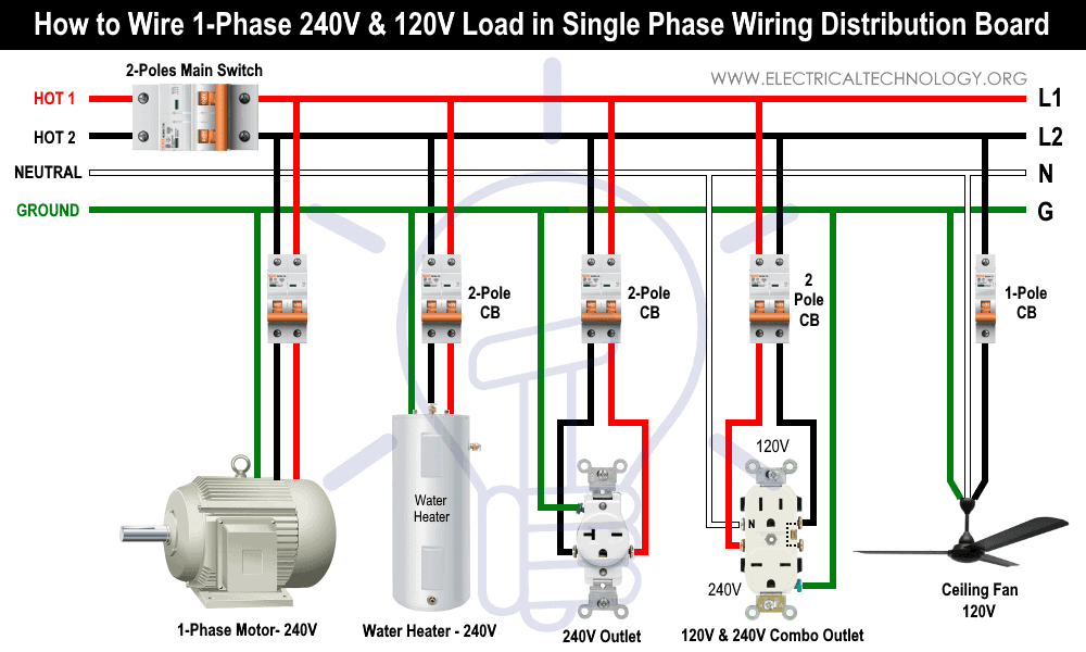
For 120V single phase circuits, the single pole circuit breaker is connected to the one hot busbar (either Hot 1 or Hot 2) and Neutral. For 240V split phase (1-Phase) circuits, the two pole circuit breaker is connected to both bus-bars i.e. hot 1 and hot 2.
The following figure shows a main service panel for 120V and 240V single phase and split phase wiring and breakers installation.
Click image to enlarge
How to Wire 120V Circuits & Breakers
The following tutorial shows how to wire 120V single phase breaker box installation in home.
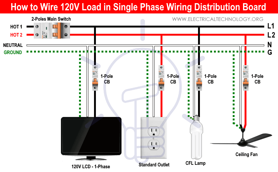
120V single phase circuits are generally used in home wiring for lighting circuits and outlet receptacles. To do so, simply mount and connect a single pole (15A or 20A) circuit breaker to any of the hot busbar (out of hot 1 or hot 2) with the help of metal tracks which hold the circuit breakers.
For example, a single pole circuit breaker is mounted on hot 1. The output of the breaker (Black) is connected to the ceiling fan. Similarly, the neutral wire (White) is also connected to the ceiling fan. Finally, the bare conductor or green wire with yellow stripe as ground is attached to the ceiling fan. For ON/OFF operation of the ceiling fan, a single pole switch should be connected only and only on hot (live) wire.
Use 12 gauge wire for 20 amp, two-poles, 120V breaker. Keep in mind that a 20A outlet can be installed on a 20 amp breaker. In other words, don’t connect a 20A outlet on a 15A circuit breaker. A 20A breaker is recommended for 16A load circuits as the breaker size must be 125% of the load amperage capacity. In simple words, 80% of the load amperes can be connected to a circuit breaker i.e. 12A load circuit should be connected to a 15A MCB circuit breaker.
Related Posts:
- How to Wire and Install an Electrical Outlet Receptacle?
- How to wire a GFCI Outlet?
- How to Wire an AFCI Outlet?
How to Wire 240V Circuits & Breakers
The following tutorial shows how to wire split phase or 240V single phase breakers in the home distribution board for residential applications.
Split phase or 240V single phase circuits are usually dedicated circuits i.e. they should connect for single load points such as dryer, stove, washing machine, air-conditioner, water pump & motors etc.
To install a 240V single phase circuit, just mount the 30A two pole circuit breaker in the metal tracks (designated for two hot busbars) which tightly holds the breakers. The two output wires from the circuit breaker connect directly to the load point. Additionally, the bare conductor as ground wire connects to the load point.
Also note that there is no need to connect the neutral wire in split phase 240V circuits (while some of the appliances need the neutral wire in 240V circuits as well, therefore, if you are not sure, refer to the user manual guide of the appliance or contact the manufacturer.
Keep in mind that use only 10 gauge wire for 30A single pole or double pole breakers. In addition, don’t use a 30A breaker for 15A, 20A or 40A outlets and load points. The same rule applies for two poles and 240V breakers i.e. use 125% amperage capacity breaker or load should be 80% of the breaker size. For example, a 30A breaker (single pole or two pole) should be connected for 24A load points.
Related Posts:
- Single Phase Electrical Wiring Installation in Home according to NEC & IEC
- Three Phase Electrical Wiring Installation in Home – NEC & IEC
In addition, it is against the code to use two separate single pole circuit breakers for 208V or 240V circuits. If you still want to connect two SP breakers as double pole for 240V circuit, the switches of both breakers should be bonded and connected together i.e. both SP breakers should be switched ON & OFF with the same common switch. Moreover, the current rating in amperes should be the same for both single pole breakers. Finally, both SP breakers should be connected to separate busbars i.e. if they are installed on the same busbar (say hot 1), the connected outlet and switches will be energized with the wrong voltage level.
Good to know: You need all four wires for grounded circuits i.e. two hot wires plus ground and neutral for 125-250 1-phase, 4-poles, 125-250V, 1-phase outlets such as L14-30R, L14-20R, 14-60R, 14-50R, 14-30R, 14-20R, 14-15R NEMA plugs and outlets.
Related Posts:
- How to Wire Combo Switch and Outlet?
- How to Wire GFCI Combo Switch and Outlet
- How to Wire an AFCI Combo Switch
Wiring Color Codes:
Keep in mind that we have used the Red color for second hot wire or blue and red for hot busbars for illustration purposes only. Please follow the National Electric Codes i.e. NEC wiring color codes or other applicable color codes related to general practice or specific area.
We have used the NEC + general practice wiring color codes in this tutorial as follows.
- Black = Hot 1 or Line 1
- Red = Hot 2 or Line 2
- White = Neutral Wire
- Green = Bare Conductor as Ground wire
The recommended colors for hot wires in 240V system are Black & Red or both as Black Colors. If a white wire has been used in 240V which carries voltage, it must be covered with a black strip or a tap wrapped around it. This way, it can be easily identified as hot wire which is used as hot wire, and not as a neutral wire.
Do not use green, green with yellow stripe or a bare conductor for those wires which carry voltage. Only and only use copper wire to reduce the resistance and heat instead of aluminum wires in the main panel box wiring.
Related Posts:
- How to Wire a Distribution Board with RCD (Residual Current Devices)
- How to Wire a GFCI Circuit Breaker?
- How to Wire an AFCI Breaker?
Safety Precautions
- Disconnect the power source (and make sure it is really swathed OFF) before servicing, repairing or installing electrical equipment. To do so, switch off the main switch in the main panel box.
- Never stand or touch wet and metal parts while repairing or installation of live circuits.
- Read carefully all the cautions and instructions and follow them strictly while doing this tutorial or any other work in practical related to electrical works.
- Always, use the right size cable and wire, proper size outlets and switch and suitable size of circuit breakers. You may also use the Wire and Cable size calculator to find the right gauge size.
- Never ever try to play with electricity (as it is dangerous and can be fatal) without proper guidance and care. Do the installation and repairing work in presence of experienced persons having vast knowledge and good practice who knows how to deal with electricity.
- Doing your own electrical work is dangerous as well as illegal in some cases. Contact the licensed electrician or the electric power supply provider before practicing any change/modification in electrical wiring connections.
- The author will not be liable for any losses, injuries, or damages from the display or use of this information or if you try any circuit in the wrong format. So please! Be careful because it’s all about electricity and electricity is too dangerous.
Related Wiring Installation Tutorials:
- How to Size a Load Center, Panelboards and Distribution Board?
- How to Determine the Number of Circuit Breakers in a Panel Board?
- How to Determine the Right Size Capacity of a Subpanel?
- Staircase Wiring Circuit Diagram – How to Control a Lamp from 2 Places?
- Corridor Wiring Circuit Diagram – Hallway Wiring using 2-Way Switches
- Tunnel Wiring Circuit Diagram for Light Control using Switches
- Hospital Wiring Circuit for Light Control using Switches
- Hotel Wiring Circuit – Bell Indicator Circuit for Hotelling
- Hostel Wiring Circuit Diagram and Working
- Godown Wiring Diagram – Tunnel Wiring Circuit and Working
- How to Wire 120V Water Heater Thermostat – Non-Simultaneous?
- Even More Electrical Wiring Installation & Tutorials


Now I know the the main trick between 120V and 240V panel circuits wiring. Thanks for that.
Hello there, Your site looks fantastic as a resource. I am an Australian electrician who would like to use your site as a resource but am not sure if ‘when relevant ‘ relates to the S.A.A (Australian Standard). ie. I am about to look into your ‘Distribution Board/Meter Panel’ wiring configuration template but is it according to our Codes? Kind Regards Jason Burns
Thank you for appreciation. As these resources clearly shows the article drawings and wiring codes are only related to IEC and NEC. There is still lit bit difference between IEC and S.A.A (Australian Standards) and if you compare, there will be little bit difference. So still you will have to check and match with the local area codes such as SAA. Thanks and regards
Does this stand true when wiring a sub panel? I’ve recently read that you cannot feed single pole breakers from a dual pole feed or main breaker. Reading your article is exactly what I’ve always followed and understood as being correct. I plan on installing a new sub panel which will be fed by 1 30a dual pole breaker, sub box will contain 2 15a and 1 20a single pole breakers for lighting and outlets. All wire and hardware requirements will be observed to fulfil 30a code requirements, do you see any issues with this installation?