How To Wire Switches in Parallel?
How to Connect Two Switches in Parallel to Control a Single Load?
In a previous basic home electrical wiring installation tutorial, we learned how to wire single way switches in series. Today, we will learn how to wire and connect two switches in parallel to control and operate a single light point.
Mostly, this is a preferred method to wire single way switches in parallel as parallel or series-parallel connections are used in common electrical wiring installation these days due to advantages over series connection.
- Related Post: How To Wire Switches in Series?
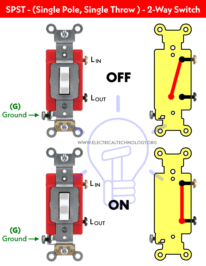
Before we go in details, we will see the basic construction and operating mechanism of single way switch which is shown in fig below:
Below is a simple step by step tutorial with schematic and wiring diagram which shows how to wire single way switches in parallel?
Requirements:
- Single Way Switches (SPST = Single Pole Single Through) x 2 No
- Lamp (Light Bulb) x 1 No
- Short pieces of cables x 5 No
Procedure:
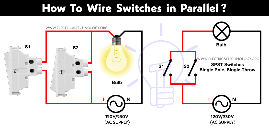
Connect the two single way switches, light bulb in parallel to the power supply as shown in fig below. Keep in mind that one of the switches S1 or S2 must be closed to complete the circuit.
If there are more switches connected in parallel with electrical appliances i.e. light point, one of them must be at ON position to operate the load. However, the light bulb won’t go off if you switch OFF one of the switches. In other words, all the switches must be closed (OFF position) to disconnect the load from the power supply.
Click image to enlarge
The circuit will complete if one of the switches out of two are at ON position. In other words, If one of the switches are close or at ON position, the light bulb will glow then. This is the same case for other loads as well to control by two (or more) single way switches connected in parallel.
Related Wiring Diagrams:
- How to Wire 4-Way Switch (NEC) & Intermediate Switch as 3-Way (IEC)?
- How to Wire Single Pole, Single Throw (SPST) as 2-Way & 1-Way Switch? IEC & NEC
- How to Wire Single Pole, Double Throw (SPDT) as 3-Way & 2-Way Switch? IEC & NEC
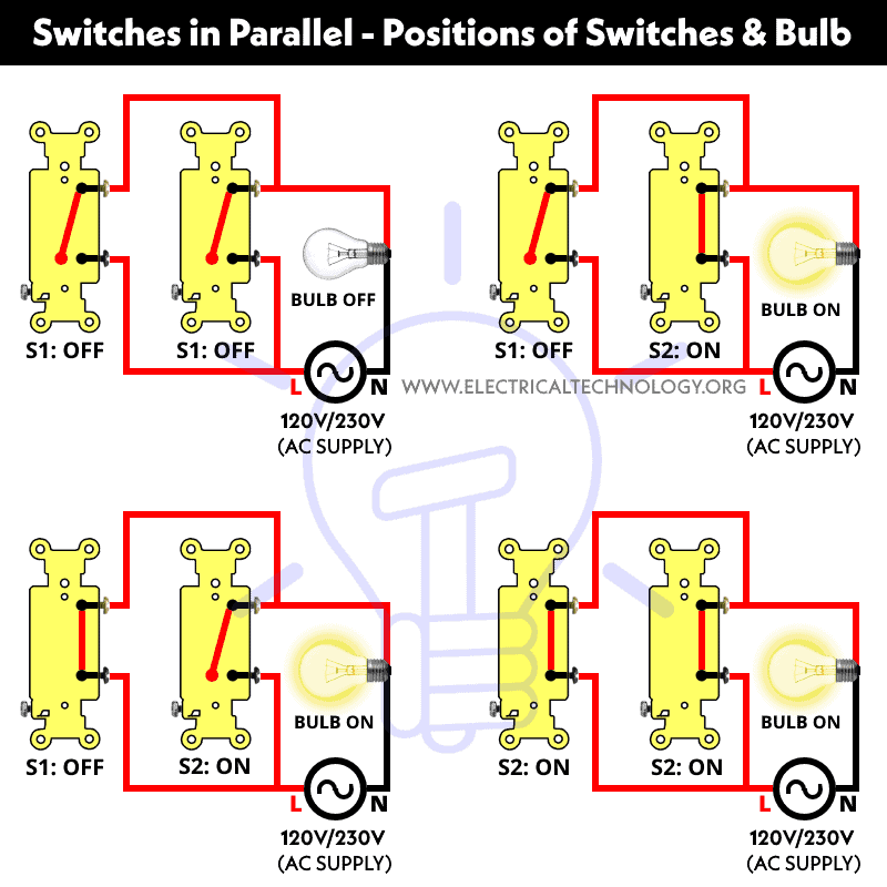
Below are the different positions of single way switches and light points when connected in parallel.
Click image to enlarge

To get the switching position in ON condition for the light bulb, the above operation is the same as the Digital Logic OR Gate truth table which is given below.
| Switch 1 | Switch 2 | Lamp Position |
| 0 = OFF | 0 = OFF | 0 = OFF |
| 0 = OFF | 1 = ON | 1 = ON |
| 1 = ON | 0 = OFF | 1 = ON |
| 1 = ON | 1 = ON | 1 = ON |
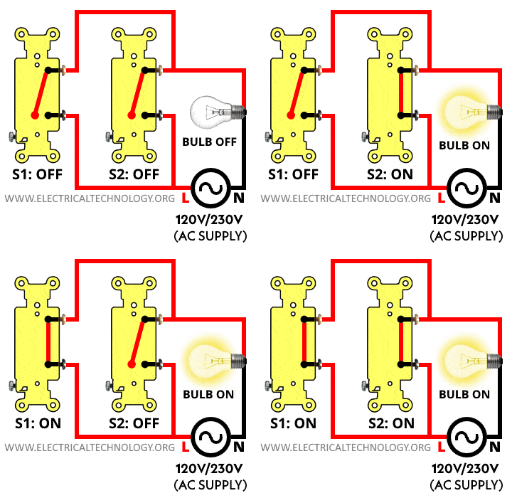
In simple words, there are four switching positions and if both the switches are at OFF position, the light bulb will not glow. On the other hand, if one of the switches is at ON position, the current will flow in the circuit as the circuit behaves like a completed circuit, hence the bulb will glow. No matter if all of the other connected switches are at OFF or ON positions.
The following gif shows the all positions of switches connected in parallel to a light bulb. It clearly shows that the light bulb is ON when any one of the switches is at ON position. If all the switches are at OFF position, The light bulb will not glow.
Here is the short video version:
Related Posts:
Good to know:
- Switches and fuses must be connected through line (Live) wire.
- Switching connections in parallel is a preferred way to wire home appliances. Instead, a parallel or series-parallel wiring method is more reliable instead of series wiring.
- More wires and cables are required in parallel wiring connections.
- It is a reliable and comfortable method of wiring.
Related Electrical Wiring Installations tutorials:
- How to Wire an Outlet Receptacle? Socket Outlet Wiring Diagrams
- How to Find the Number of Outlets on a Single Circuit Breaker?
- How to Find Voltage & Ampere Rating of Switch, Plug, Outlet & Receptacle
- How to Wire a Pilot Light Switch? Wiring of 2 & 3 Way Neon Light Switches
- How to Wire Combo Switch and Outlet? – Switch/Outlet Combo Wiring Diagrams
- How to Wire an AFCI Combo Switch – AFCI Switch Wiring Diagrams
- How to Wire GFCI Combo Switch and Outlet – GFCI Switch/Outlet Wiring Diagrams
- How to Control Water Heater using Switches?
- How to Wire a Ceiling Fan? Dimmer Switch and Remote Control Wiring
- How to Wire Auto & Manual Changeover & Transfer Switch – (1 & 3 Phase)
- Automatic Bathroom Light Switch Circuit Diagram and Operation
- Staircase Wiring Circuit Diagram – How to Control a Lamp from 2 Places by 2-Way Switches?
- 2 Way Switch – How to Control One Lamp From Two or Three Places?
- How to Control a Lamp by a Single Way or One-Way Switch?
- How to control each lamp by separately switch in parallel lighting circuit?
- How to Control One Light Bulb from Five or Six Different Places using Intermediate Switches?
- Corridor Wiring Circuit Diagram – Hallway Wiring using 2-Way Switches
- Hospital Wiring Circuit for Light Control using Switches
- Hostel Wiring Circuit Diagram and Working
- Godown Wiring Diagram -Tunnel Wiring Circuit and Working
- Tunnel Wiring Circuit Diagram for Light Control using Switches
- How to Wire a UK 3-Pin Plug? Wiring a BS1363 Plug
- How to Wire a UK 3-Pin Socket Outlet? Wiring a BS1363 Socket
- How to Wire a Twin 3-Pin Socket Outlet? Wiring 2-Gang Socket
- How to Wire Combo Switch and Outlet? – Switch/Outlet Combo Wiring Diagrams
- Switch and Push Button Symbols
- Basic Electrical Wiring Diagrams


This is helpful for those who have no basic knowledge in electrical, your instruction is easy to follow. Pls. keep posting.<br /><br /><a href="http://www.woertz.ch/" rel="nofollow">woertz</a><br />
Thanx Dear,,We will try to our best…
what is the help of parallel wiring………..?
Thanks admin for this wonderful post, full of ideas about electrical. The post is written in very a good manner and it entails many useful information for me. I appreciated what you have done here. <br /><a href="http://www.electricalserviceteam.com" title="" rel="nofollow">Electrical Services</a><br />
Thanks..
Welcome Dear
i am unable to get the application of series and parallel lamp switch..
Really i too why one should use this parellel combination manes..<br />
Hi! My old house had a light switch arrangement that still has me curious about its workings! Perhaps you can illuminate us with a schematic and/or explanation!<br /><br />We had a light above the stairs, with a switch upstairs, and a switch downstairs. Either switch, when flipped, no matter whether the light was on or off, would turn the light on if it was off, and off if it was on. Can you
Sounds to me like you have incorrect polarity. Using a very basic example, it means you negative and positive are the wrong way around. (Negative to positive and positive to negative). Try looking at your switches and make sure the live goes to live and the negative goes to negative. Hope this helps.
What you’re describing is a simple 3 way circuit. Nothing wrong with it at all. It requires a special kind of switch and a “traveler” wire between the two of them to work.
Note that it is NOT a parallel or series circuit. It is a 3 way circuit.
i need design of my newly construct room with singly phase required connections as below:<br /><br />main panel contain 1 Fan Switch , 3 Bulb Switch 3 different points, at least 4 sockets required on main panel.<br /><br />2nd panel required for my Computer containing 6 sockets with 2 switches.<br /><br />3rd for electrical iron.<br /><br />kindly suggest me the basics of electrical wiring or
I think it only for concept building otherwise no use of this circuit configuration
IN A SINGLE PHASE CONNECTION, CAN U HAVE 2 SWITCHES ON 2 DIFF MCBS POWERING THE SAME BULB.IN A PARALLEL CIRCUIT
what happen if we switch on both switches at a time
what will happen if the two switches are in ON state
Why we use 2 switch’s for a single bulb
it does not happen ….
why we use here 2 spst switch
I have an overhead ceiling mounted light fixture in my hallway. I have a switch on one of the ends of the hall that I use to turn the light on and off with. The other light switch on the other end of the hall does nothing. I would like to have the capability to turn the light on and off using both switches if I need to. Both switches were wired to do that when house was built
I would also like to turn the light on with one switch and turn it off with the other switch. Any ideas?
Scott
You can use what are called 2-way switches. The usual 12/2 with ground has to be replaced with 12/3 with ground. The extra wire is necessary for the 2-way switch to work. The switches look very much like regular switches but the wiring connections are different.
If you are unfamiliar with this type of circuit, it is easy to get the wiring wrong. In that case it would be better to get an electrician to do it. I wired a house about 40 years ago that had six circuits like this and I had no problem. Since that time I have wired several of these circuits
I have a 3 phase pump mtr powered by an inverter that converts single phase 220 into 3 phase. the 220 to the inverter is controlled by an irrigation timer that sends 24vac to a relay which gives power to the inverter.
I would like to add a second method for turning on the motor. This would be a pressure sensing circuit that would start the mtr through inverter when water pressure falls below a preset number.
It could happen that the inverter would be running the pump when the timer clicked on. This would mean two parallel “switches” would both be on. The switches in this case would be two dpst relays each controlled by their separate sensing device (time clock/pressure switch)and separate coil voltage sources. The 220 power source would be the same mains power.
This seems right to me. Am I missing something?Naturally the hot legs must not cross…or kaboom.
So if one switch is closed, the other is effectively useless?
I can definitely see why you would want to set up a parallel system with AC power and some switches. It seems like such a simple system could could be expanded upon to create a much more intricate service. I can see this functioning to power a something as large as a city grid.
very good explanation
Thank you for this explanation. This is helpful for my use case where i would want to add a smart switch for a bulb but would want the bulb to turn on either with the smart switch or with the physical switch. however, i would turn off only when both are off.
Could you confirm that this would not have any impact if both the switches are on and ideally the result would be the same as if either one was on.?
where we use switches in parallel and where we can use switches in series and its benefit
The table may need update
3rd row, should be on
Updated. Thanks for correction.