What is the Role of Capacitor in AC and DC Circuit?
What is the Role of Capacitor in AC and DC Circuit?
Role of Capacitor in AC Circuits:
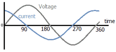
In an AC circuit, capacitor reverses its charges as the current alternates and produces a lagging voltage (in other words, capacitor provides leading current in AC circuits and networks)
Role of Capacitor in DC Circuits:
In a DC Circuit, the capacitor once charged with the applied voltage acts as an open switch.
- Related Post: Difference Between a Battery and a Capacitor
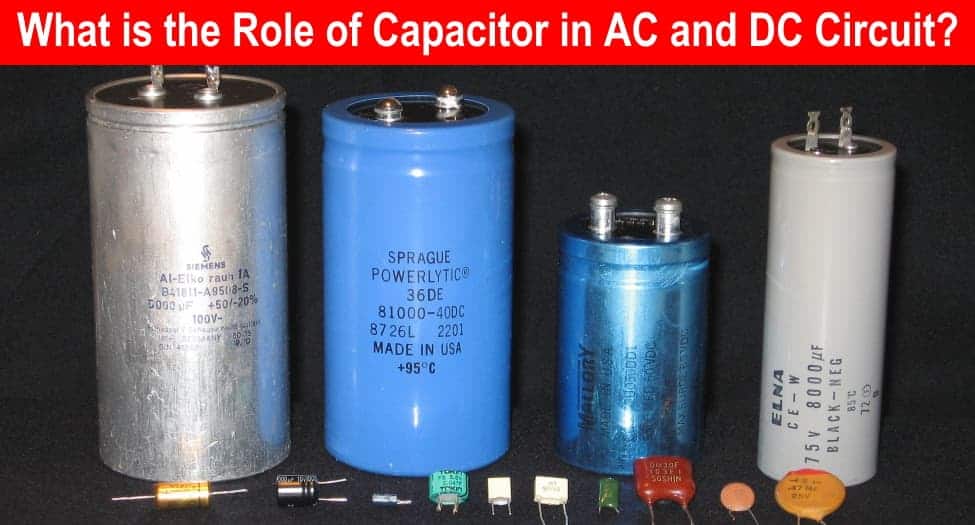
Let’s explain in detail, but we will go back to the basics of capacitor first to discuss the matter.
- Related Post: Difference Between Capacitor and Supercapacitor
What is a Capacitor?
The capacitor is a two terminal electrical device used to store electrical energy in the form of electric field between the two plates. It is also known as a condenser and the SI unit of its capacitance measure is Farad “F”, where Farad is a large unit of capacitance, so they are using microfarads (µF) or nanofarads (nF) nowadays.
A capacitor is similar to a battery, as both stores electrical energy. A capacitor is a much simpler device that can’t produce new electrons, but stores them. Inside the capacitor the terminals connected with the two metal plates separated by dielectric material (such as waxed paper, mica, and ceramic), that separate the plates and allows them to hold opposite electrical charges maintaining electrical field.
- Related Post: What Happens When an AC Line Touches a DC Line?
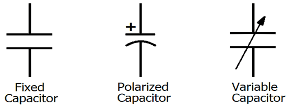
Capacitors can be useful for storing charge and quickly discharging into the load. In a simple way, a capacitor also work as a small rechargeable battery. The electrical equivalent symbol of different types of capacitor is given below:
Now, we know the concept of the capacitor’s charging and its structure but, do you know what Capacitance is? the capacitance is the ability of a capacitor to stores the charge into it. There are some factors which affect the capacitance.
- Plate’s Area
- Gap between the plates
- Permittivity of the insulating material
Related Post: Capacitor & Types Of Capacitors | Fixed, Variable, Polar & Non-Polar
A capacitor has wide range of applications in electronics, such as Energy Storage, Power Conditioning, Power factor correction, Oscillators and filtration.
In this tutorial we will explain you, how you can use a capacitor in an electronic circuit. There are three ways to connect a capacitor in an electronic circuit,
- Capacitor in Series
- Capacitor in Parallel
- Capacitor in AC Circuits
- Capacitor in DC Circuits
Related Post: Capacitors MCQs with Explanatory Answers
How Capacitor Works?
Working and Construction of a Capacitor
Whenever voltage is applied across its terminals, (Also known as charging of a capacitor) current start to flow and continue to travel until the voltage across both the negative and positive (Anode and Cathode) plates become equal to the voltage of the source (Applied Voltage). These two plates are separated by a dielectric material (such as mica, paper, glass, etc. which are insulators), which is used to increase the capacitance of the capacitor.
When we connect a charged capacitor across a small load, it starts to supply the voltage (Stored energy) to that load until the capacitor fully discharges.
Capacitor comes in different shapes and their value is measured in farad (F). Capacitors are used in both AC and DC systems (We will discuss it below).
- Related Post: AC or DC – Which One is More Dangerous And Why ?
Capacitance (C):
Capacitance is the amount of electric charge moved in the condenser (Capacitor), when one volt power source is attached across its terminal.
Mathematically,
Capacitance Equation:
C=Q/V
Where,
- C = Capacitance in Farads (F)
- Q = Electrical Charge in Coulombs
- V = Voltage in Volts
We will not go in detail because our basic purpose of this discussion is to explain the role and application/uses of capacitors in AC and DC systems. To understand this basic concept, we have to understand the basic types of capacitor related to our topic (as there are many types of capacitor and we will discuss capacitor types latter in another post because it is not related to the question).
Related Posts:
Capacitors in Series
How to Connect Capacitors in Series?
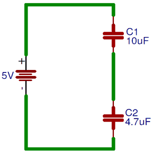
In series no capacitor is directly connected to the source. To connect them in series you need to join them end to end, as shown in the below image,
When you connect the capacitors in series the total capacitance is decreased. Hence, the connection is in series so the current through the capacitors will be equal. Also, the charge stored by plate of capacitor will be same because it is coming from the adjacent capacitor’s plate.
Hence,
IT = I1+I2+I3+…+In
and
QT = Q1+Q2+Q3+…+Qn
Now, for finding the value of capacitance of the above circuit, we will apply Kirchhoff’s Voltage Law (KVL), then we have
VT =VC1+VC2+VC3
As we know that, Q = CV
And V = Q/C
So,
(Q/ CT) = (Q/ C1) + (Q/ C2) + (Q/ C3)
Hence,
1/CT = (1/C1) + (1/C2) + (1/C3)
For nth no. of capacitor connected in series,
For two capacitors in series, the formula will be
CT = (C1 x C2) / (C1 + C2)
Now, you can find the capacitance of the above circuit, by using the formula,
Here, C1 = 10uf and C2 = 4.7uF
So, CT = (10 x 4.7) / (10 + 4.7)
CT = 47 / 14.7
CT = 3.19uF
Capacitors in Parallel
How to Connect Capacitors in Parallel?
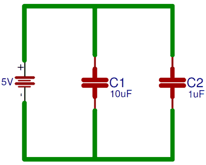
In parallel every capacitor is directly connected to the source, as you can see in the below image,
When you connect the capacitors in parallel the total capacitance is equal to the sum of all the capacitor’s capacitance. Because the top plate and bottom plate of all capacitor connected together, due to this the plate area is also increased.
The total current in the parallel circuit will be equal to the current across every capacitor.
By applying Kirchhoff’s law,
IT = I1 + I2 + I3
Now, the current across the capacitor is expressed as,
I = C (dV /dt)
By solving the above equation
CT = C1 + C2 + C3
And, for nth no. of capacitor connected in series,
CT = C1 + C2 + C3 + … + Cn
Now, you can find the capacitance of the circuit, by using the above formula,
Here, C1 = 10uf and C2 = 1uF
So, CT = 10uF + 1uF
CT = 11uF
Related Posts:
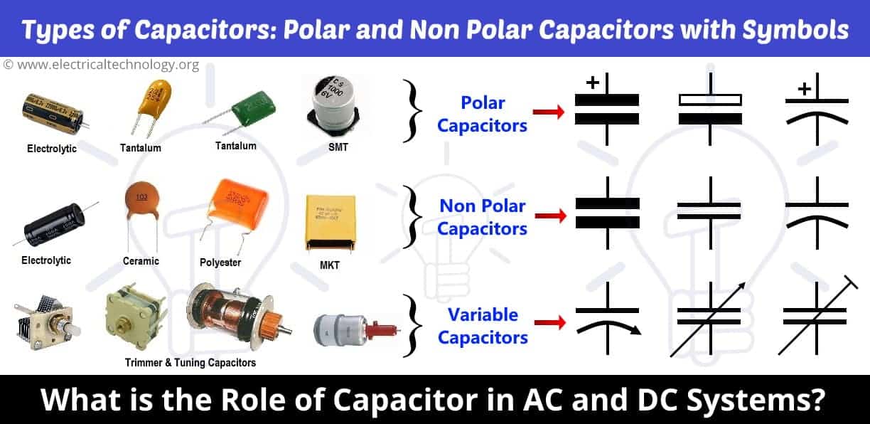
Polar and Non-Polar Capacitor
Non Polar Capacitor: (Used in both AC and DC Systems)
The Non Polar capacitors can be used in both AC and DC systems. They can be connected to the power supply in any direction and their capacitance does not effect by the reversal of polarity.
Polar Capacitor: (Only used in DC Circuits and Systems)
This type of capacitor is sensitive about their polarity and can be only used in DC systems and networks. Polar Capacitors don’t work in the AC system, because of the reversal of polarity after each half cycle in AC supply.
Role of Capacitors in AC Circuits
The capacitor has lots of applications in AC systems and we will discuss few uses of capacitor in AC networks below.
Transformer less power supply:
Capacitors are used in transformer less power supplies. In such circuits, the capacitor is connected in series with the load because we know that the capacitor and inductor in pure form does not consume power. They just take power in one cycle and deliver it back in the other cycle to the load. In this case, it is used to reduce the voltage with less power wastage.
Split phase induction motors:
The capacitors are also used in induction motor to split a single phase supply into a two phase supply to produce a revolving magnetic field in the rotor to catch that field. This type of capacitor is mostly used in household water pumps, Fans, air conditioner and many devices which need at least two phases to work.
Power Factor Correction and Improvement:
There are lots of advantages of power factor improvement. In a three phase power systems, capacitor bank is used to supply reactive power to the load and hence improve the power factor of the system. Capacitor bank is installed after a precise calculation. Basically, it delivers the reactive power which was previously traveled from the power system, hence it reduces the losses and improves the efficiency of the system.
- How to Convert Capacitor Farads into kVAR & Vice Versa (For Power factor improvement)
- How to Calculate the Suitable Capacitor Size in Farads & kVAR for Power factor Improvement
Capacitors in AC Circuits
How to Connect a Capacitor in AC Circuit?
In DC Circuit, the capacitor charges slowly, until the charging voltage of a capacitor is equal to the supply voltage. Also, in this condition the capacitor doesn’t allow the current to pass through it after it gets fully charged.
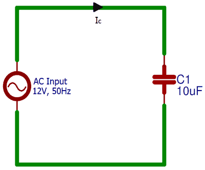
And, when you connect a capacitor across an AC source, it charges and discharges continuously, due to continuous change in the voltage levels. Capacitance in AC circuits is depends upon the frequency of the supplied input voltage. Also, if you see the phasor diagram of an ideal AC capacitor circuit you can observe that, current leads the voltage by 90⁰.
In AC capacitor circuit, current is directly proportional to the rate of change of supplied input voltage, which can be expressed as,
I = dQ /dt
I = C (dV / dt)
Now, we will calculate the capacitive reactance in AC circuit.
As we know that, I = dQ/dt and Q = CV
And, the AC input voltage in the above circuit will be expressed as,
V = VmSinwt
So, Im = d(CVmSinwt)/dt
Im = C*VmCoswt*w (after differentiation)
Im = wC VmSin (wt + π/2)
At, w =0, Sin (wt + π/2) = 1
Hence,
Im = wCVm
Vm / Im = 1/wC (where, w = 2πf and Vm / Im = XC)
Now, to calculate the capacitive reactance of the above circuit,
XC = 1 / [ 2π (50 Hz)(10-6 F) ]
XC = 3183.09 Ω
Related Post: What is the difference between a battery and a capacitor?
Role of Capacitors in DC Circuits
Power conditioning:
In DC systems, capacitor is used as a filter (mostly). Its most common use is converting AC to DC power supply in rectification (such as bridge rectifier). When AC power is converted into fluctuating (with ripples i.e. not a steady state with the help of rectifier circuits) DC power (Pulsating DC) in order to smooth and filter out these ripples and fluctuation, DC Polar capacitor is used. Its value is calculated precisely and depends on the system voltage and the demand load current.
- Related Post: What is the Role of Capacitor in a Ceiling Fan?
Decoupling Capacitor:
Decoupling capacitor is used, where we have to decouple the two electronics circuits. In other words, the noise generated by one circuit is grounded by decoupling capacitor and it does not affect the performance of other circuit.
Coupling Capacitor:
As we know that Capacitor blocks DC and allows AC to flow through it (we will discuss it in the next session that how does it happens). So it is used to separate AC and DC signals (also used in the filter circuits for the same purpose). Its value is calculated in such a way that its reactance is minimized on the basis of frequency, which we want to pass through it.
Coupling Capacitor is also used in filters (ripple remover circuits like RC filters) to separate AC and DC signal and removes the ripples from pulsating DC supply voltage to convert it into pure DC voltage after rectification.
You may Also read:
- How to Check a Capacitor with Digital Multimeter
- General Capacitor Nameplate Rating (Electrolytic Capacitor)
- Capacitor Code: How to Find the value of Ceramic Capacitors?
- What Happens to the Battery with Reverse Polarity Wiring Connection
- What Happens if a Battery is Connected to the AC Supply?
- What Happens if We Connect a Polar Capacitor the Wrong Way?


It might be great if this article should be explained well. Anyway thanks
great job…
can u pls brief operation of Capacitor in AC. It opposes the change of voltage. how it works in AC
Hi, literally ac increases to a maximum in positive V+ then to Zero, again to maximum negative V- then to zero in that cycle….Now a capacitor connected accross an ac will charge to it’s maximum Value in the first-half cycle.
as Current increases to it’s maximum V+. As current drops to zero in the second half, the capacitor is still charged and takes a “given time lag” to discharge. Now when the current start to increase to V-, the capacitor is not yet fully discharged and Hence the current in the load across it doesn’t completely goes to zero, and this is the smoothing characteristic of the capacitor. NB “Time lag ” known as time constant is equivalent to The Capacitance of the capacitor X the Load Resistance…
very useful
I’m agree with aramuthan karuna.. many topics are skipped by saying they will be further explained so waiting for that explanation.. especially working of capacitor in AC. Thank you…
Whenever voltage is applied across its terminals, (Also known as charging of a capacitor) current start to flow and continue to travel until the voltage across both the negative and positive (Anode and Cathode) plates become equal to the voltage of the source (Applied Voltage). These two plates are separated by a dielectric material (such as MICE. paper, glass, etc. which are insulators), which is used to increase the capacitance of the capacitor.
I Believe it was stating MICA instead of mice ?
We would be glad if it is explained in more detail. But still this is useful information only.
i am studying on how to eliminate or reduce voltage ripples after rectification this article has enlightened me to search on RC filters in more detail. Thank you author
I think there is a small mistake at the end. Isn’t it? “… To convert pulsating DC into pure DC after rectification…”
You stated that capacitors and batteries store electricity WRONG. Only capacitors. ( condensors and a leddy jar) store eldctricity. I was taught over 50 years ago that batteries store chemical energy that is converted to electricity. Great article.
Good job
I agree with Lorant Incze. In the final sentence of the article, you state: Coupling Capacitor is also used in filters (ripple remover circuits like RC filters) to separate AC and DC signal and removes the ripples from pulsating DC supply voltage to convert it into pure AC voltage after rectification.
I believe you meant to say: Coupling Capacitor is also used in filters (ripple remover circuits like RC filters) to separate AC and DC signal and removes the ripples from pulsating DC supply voltage to convert it into pure DC voltage after rectification.
After rectification, there should no longer be AC, but only DC. Please edit the article, as this could be very confusing to someone not recognizing the error.
I’m finding your explanations very helpful! Thank you!
Thank you for the correction. Updated now.