Two-Speed, One-Direction, 3-Phase Motor Power & Control Diagrams
How to Control a Dual/Tap-Wound 3-Phase Motor for 2-Speed and 1-Direction using Dahlander Connection?
Three-phase motors are widely used in industrial applications due to their efficiency and robustness. Often, there’s a need for controlling the speed of these motors while maintaining a single direction of rotation. This wiring tutorial shows how to control a tap-wound 3-phase motor for two-speed and one-direction using Dahlander connection for contactors with the help of schematic, power, control and wiring diagrams.
Two-Speed Motor Control:
Two-speed control of a three-phase motor involves running the motor at two different speeds, often referred to as high speed (HS) and low speed (LS). This is achieved by connecting the dual or tap wound motor’s winding in a specific configuration (Dahlander connection) to adjust the magnetic field and, consequently, the motor’s speed.
The two-speed control is usually accomplished by changing the arrangement of the motor windings from the main to star (Y) connection and delta (Δ) connection, altering the impedance and hence the speed.
Related Posts:
- Two-Speed, Two-Directions, 3-Phase Motor – Power & Control Diagrams
- Three-Speed, One-Directions, 3-Phase Motor – Power & Control Diagrams
Components Needed
- Three-Phase Dual / Tap-Wound Motor
- 3 Nos. of Contactor
- Thermal Overload Relay
- 3-P MCCB
- 2-P MCB
- 3 Nos. of pushbuttons
- Single-Phase & Three Phase Supply
- Wires & Cables
Wiring & Control of Dual/Tap Wound Motor for 2-Speed Operation
At the initial stage, all contactors are de-energized.
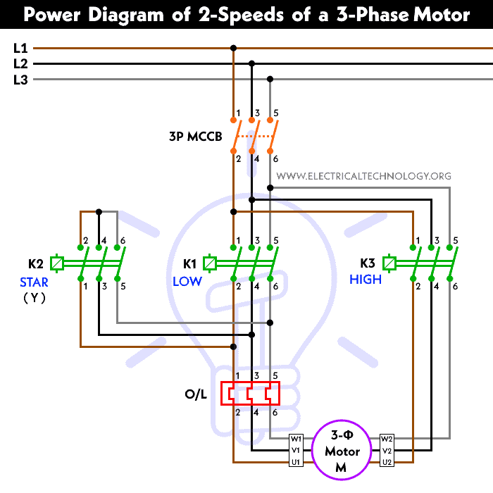
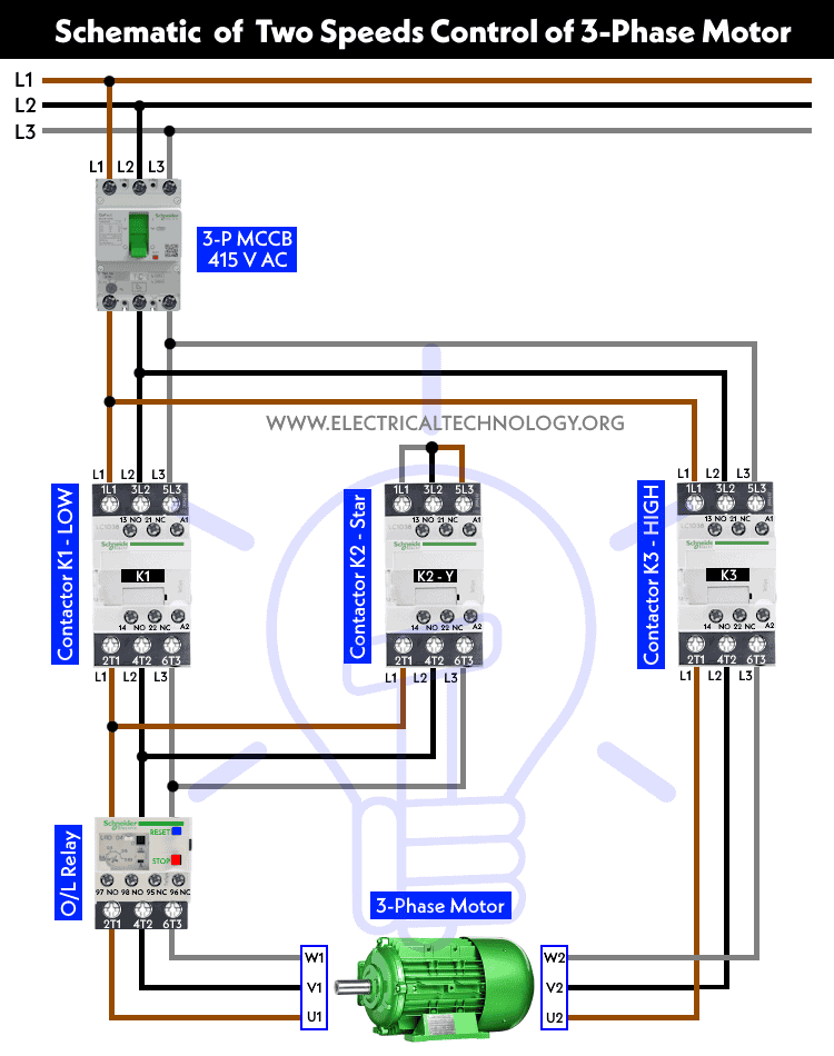
- When K1 is energized, the motor runs at low speed.
- When K2 and K3 are energized, the motor runs at high speed.
Power Diagram
Schematic Wiring Diagram
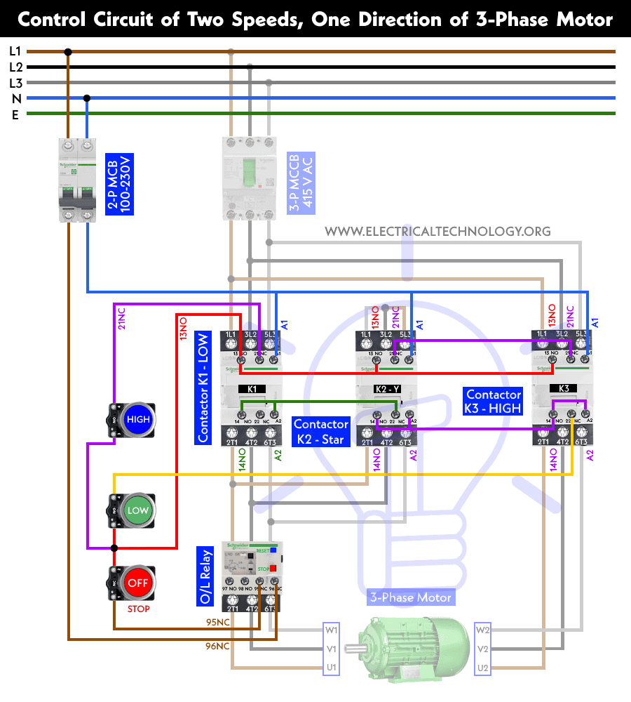
Control Wiring Diagram
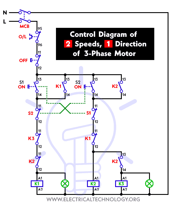
Control Circuit Diagram
Construction of the Power & Control Circuit:
To achieve two-speed, one-direction control of a three-phase motor using contactors, follow these steps:
Power & Control Circuit Diagram
Draw a schematic diagram and wire the power and control circuit as shown in the figures below. This circuit will consist of a power supply, a low speed contactor (K1), high-speed contactors (K2 and K3), a thermal overload relay (OLR), and the three-phase tap wound motor.
Low-Speed Contactor (K1):
The main contactor for low speed (K1) connects the motor to the power supply. When energized, it completes the circuit and allows current to flow through the motor windings. When the K1 is energized, the motor runs at low speed.
The K1 is controlled by a start pushbutton. If you release the pushbutton after pressing it, the contactor K1 is still energized. Thanks to the interlocking via auxiliary contacts. ,
High-Speed Contactor (K2 & K3):
The high-speed contactor (HSC) and low-speed contactor (LSC) are connected in parallel with each other. These contactors control the motor’s speed by switching between the star (Y) and delta (Δ) configurations of the motor windings. When the K2 and K3 are energized, the motor runs at high speed.
Thermal Overload Relay (OLR) The thermal overload relay protects the motor from overheating. It measures the motor’s current and trips if the current exceeds a predefined value, preventing motor damage. It’s wired in series with the K1 control circuit.
Control Logic:
Design a control logic that ensures the K1 is energized only K2 and K3 are de-energized by interlocking, preventing both contactors from being energized simultaneously. This prevents a short circuit in the motor windings due to incorrect wiring.
Control Inputs Connect start/stop. LOW and HIGH pushbuttons to the control circuit to initiate and halt motor operation. Connect these buttons in series with the K1 and O/L relay coil.
Working & Operation of Two-Speed Motor Control
This control circuit includes three contactors and three push buttons (Stop, S1, and S2). Pushbuttons S1 and S2 each have two contact blocks (one NO and one NC). Let’s analyze the circuit when we press S1 for slow speed.
Low Speed
- The contacts in parallel to K1 change their state from open to closed.
- Simultaneously, the S1 and K1 on the right side change their state from closed to open.
- As a result, only K1 is energized, and the motor runs at low speed.
- If the pushbutton is released by the operator, the K1 contactor will remain energized due to interlocking via auxiliary contacts.
High Speed
- When S2 is pressed, the contacts of K2 close from an open state, energizing the K2 contactor.
- The auxiliary contacts close and energize the K3 contactor.
- This happens because the auxiliaries of K2 and K3 contactors are energized.
- Consequently, the contacts change their state from closed to open on the left side.
- If the operator releases the S2 pushbutton, the motor continues to run at high speed.
Related Posts:
- Star-Delta (Y-Δ) 3-phase Motor Starting Method by Automatic star-delta starter with Timer.
- Three Phase Motor Connection STAR/DELTA Without Timer – Power & Control Diagrams
- Three Phase Motor Connection Star/Delta (Y-Δ) Reverse / Forward with – Timer Power & Control Diagram
- Starting & Stopping of 3-Phase Motor from more than One Place Power & Control diagrams
- Control 3-Phase Motor from more than Two buttons – Power & Control Diagrams
- ON / OFF Three-Phase Motor Connection Power & Control Schematic and Wiring Diagrams
- Three Phase Motor Connection Reverse and Forward – Power and Control wiring diagrams
- Three Phase Slip Ring Rotor Starter – Control & Power Diagrams
- Even Motor Power & Control Circuit Diagrams for 3-Phase Motor


Good Evening,
I want to know the fundementals behind 2 speed control in the motor. Will it be applicable for slip-ring motors also?
Thanking you,
please tell me fundamental of 2 speed 1 direction of 3 phase motor,what is S1 AND S2 and its working.kindly please tell me
It is very helpful thanks.but please can you tell me what S1 and S2 means?(it is not written in the description).
S1= start
S2= stop
s1-speed 1
s2-speed 2
off push switch – stop (should be NC)
Hi can I please get a simple control and power diagram for a 2speed. Motor 3phase thanks
witch overload should be greater high speed or low speed
What’s the ratio between low & high speed?
please is it the normal stop and start button can be use for the control and many stop and start button required for this??????
Hi guys. Please explain to me if I must really put a contactor on my 3 phase motor. And can I not just run it straight without a contactor. 2 contactors burned out in one day but nothing wrong with motor. motor is a hi low 3 phase motor on a air compressor.
Please explain to me.
You need a contactor for controls. Check the input voltage of your contactor coils and ensures it’s the same with the voltage that’s powering it.
A three phase motor had Star Delta written on the name plate but could not work in 2 speeds (star-delta). It was correctly connected.
What could be the problem?
How to combine boltages from two DC dynamo wheels and supply them outside. Like 5 Bolt +5 Bolt = 10 Bolt
Kindly email me the diagrams for star deltor and direct online for a 3speed 1directon 3ph motor, have two of them in a Bow Cutter. One contactor burnt for high speed and a replced contactor does not engange, originally the coils re fed with a nutural and the one i replaced is only working with a phase. please help how to go about this
i want to know the working principle of power system and is their a right diagram spacialy star connection k2 with low k1 and is their wanted overload after motor?
and there is some fault the control diagram.So i can’t understand both diagram.i want your answer.
Thank you
Here use 3 contact
Why here low speed during time 2 contact energy (k1,k2)and high speed running time(k2)
Only one
And why we use low speed time star winding
High speed time with out Star winding
Say something about it as soon as possible
Here what is U1,V1,W1,U2,V2 and W2. Can anyone please explain. Thanks.
way 2 speeds 1 direction 3 phase motor power not working law speed?
please tell me fundamental of 2 speed 1 direction of 3 phase motor,what is S1 AND S2 and its working.kindly please tell me
how this logic will work, when K1 is ON other contactor will be open so when K1 is passing the supply to one end of motor other end is open because K3 is open so how the motor will start. And what is the logic behind the low and high speed.
I want to know how to run low speed with only K1contactor.Please explain me.I hope your explanation.