Three Phase Slip Ring Motor Wound Rotor Starter – Control & Power Diagrams
Power and Control Diagrams of Self Start Slip Ring 3-Phase Induction Motor Wound Rotor Starter
Three-phase slip-ring (aka wound rotor) induction motors are widely used in heavy load and torque applications. While, three-phase induction motors can be challenging to start, especially when they are driving heavy loads. During startup, the rotor experiences a large inrush current, which can lead to overheating and mechanical stress. To mitigate these issues, various starting methods are employed, and one such method is the slip-ring rotor starter. In the following wiring guide, we will show how to control the starting and speed control of the three-phase wound rotor (slip-ring) induction motor with the help of schematic, power and control wiring diagrams.
What is a Slip Ring Motor?
A slip ring motor, also known as a wound rotor motor, is a type of three-phase induction motor with a unique rotor design. Unlike the standard squirrel-cage rotor, a slip ring motor has two windings, stator and rotor where the rotor windings connected to external slip rings, which are in turn linked to resistors. This configuration allows for greater control over the motor’s starting characteristics and speed regulation.
By adjusting the resistance in the rotor circuit, slip ring motors can provide smoother starting, higher torque at low speeds, and improved control over the motor’s performance, making them well-suited for applications where precise speed and torque control are essential, such as in heavy industrial machinery and certain specialized applications.
- The rotor windings are connected to the external rotor resistances, that’s why it is known as slip ring motor. These external resistances automatically adjusts and runs the motor at full load and speed.
- The slip ring induction motor has a high starting torque because the resistance of the motor winding increases with the addition of external resistance. The starting torque is enhanced as the power factor of the rotor circuit improves during the startup process.
- The slip ring induction motor has its rotor winding connected to an external variable resistor using slip rings. This configuration reduces the starting current during the initial stage of motor startup.
Related Posts:
- Reverse-Forward of 3-Phase Motor using DOL Starter
- Reverse-Forward Star/Delta Starter for Three Phase Motor
Components Needed
- Three-Phase Slip-Ring Motor
- 4 Nos. of Contactors
- Thermal overload Relay
- 3P-MCCB
- ON-OFF Pushbuttons
- Three Phase Power Supply
- Wires & Cables
Power & Control Wiring Diagrams
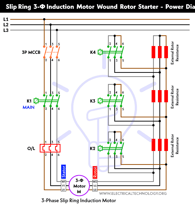
Power Diagram
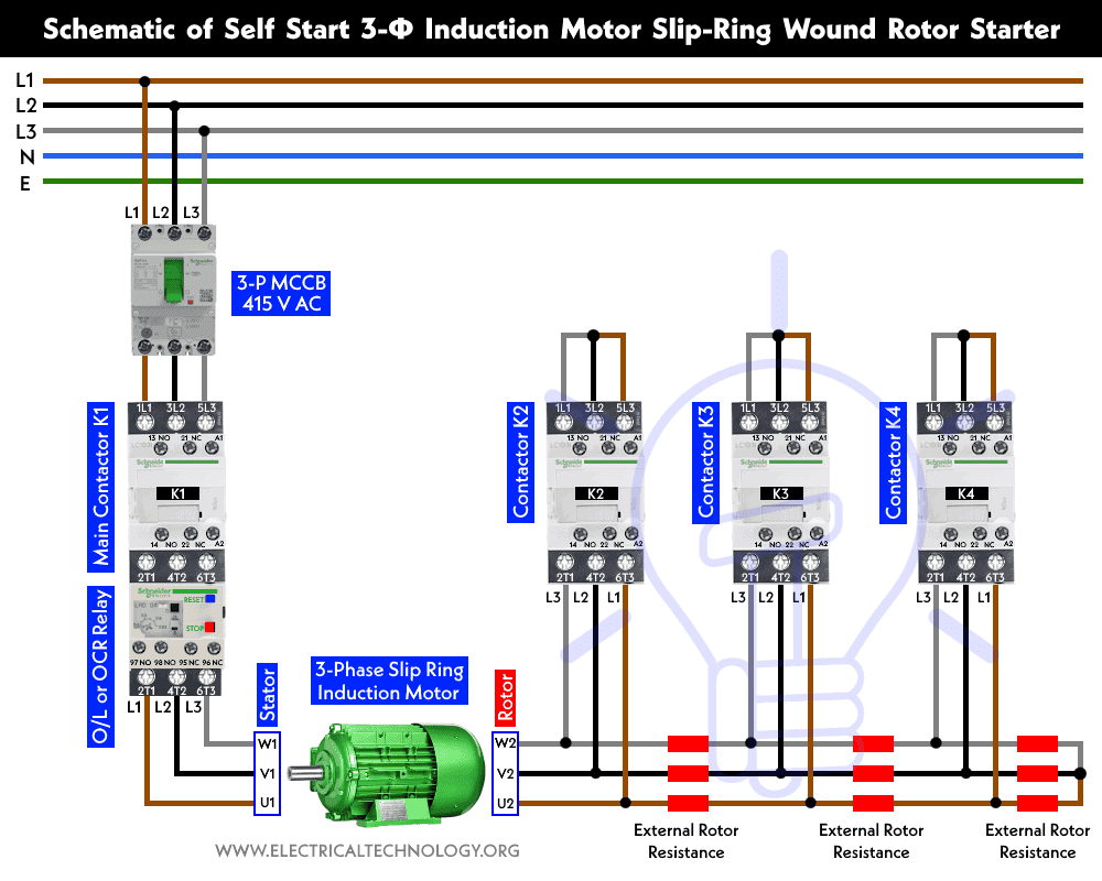
Schematic Diagram
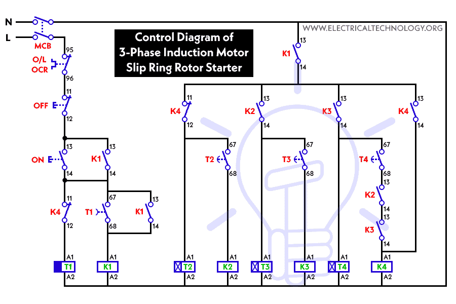
Control Circuit Diagram
Related Posts:
- Auto & Manual Control of 1-Phase Water Pump Motor using Float Switch
- Auto & Manual Control of 3-Phase Water Pump Motor using Float Switch
What is a Slip Ring Rotor Starter?
A slip ring rotor starter, also known as a wound rotor starter, is a specialized device used to control the starting and speed of a three-phase induction motor. It consists of several key components:
- Rotor with Slip Rings: In a slip ring rotor starter, the rotor of the induction motor has three slip rings mounted on its shaft. These slip rings are electrically insulated from the rotor and are connected to external resistors.
- External Resistors: The slip rings are connected to external resistors via brushes. These resistors are often made of wire-wound ceramic or other high-resistance materials. The resistors are placed in series with the rotor windings.
- Control Panel: The control panel houses the necessary electrical components for operating the starter. This includes contactors, switches, and sometimes a rheostat for controlling the resistance in the rotor circuit.
How Does a Slip Ring Rotor Starter Work?
The operation of a slip ring rotor starter can be broken down into several steps:
- Starting: When the motor is initially started, the slip rings are short-circuited. This means that the rotor windings are connected directly to the stator windings, creating a high resistance to the rotor current. As a result, the rotor experiences a reduced inrush current during startup, preventing excessive heating and mechanical stress.
- Speed Control: As the motor accelerates, the resistance in the rotor circuit is gradually decreased. This is typically done by adjusting the position of the brushes or using a rheostat. Reducing the resistance in the rotor circuit allows the rotor to approach synchronous speed more quickly.
- Running: Once the motor reaches near synchronous speed, the slip rings are completely disconnected from the rotor circuit. At this point, the motor operates like a standard squirrel-cage induction motor, running efficiently at its rated speed.
Related Posts:
- How to Start & Stop a 3-Phase Motor from Multiple Locations?
- How to Control a 3-Phase Motor from Multiple Places?
Advantages of Slip Ring Rotor Starters
Slip ring rotor starters offer several advantages, making them suitable for specific applications:
- Reduced Starting Current: By introducing resistance in the rotor circuit during startup, slip ring rotor starters significantly reduce the inrush current, preventing voltage drops and minimizing mechanical stress.
- Smooth Starting and Speed Control: These starters provide smooth acceleration and allow precise control of the motor’s speed during startup, which is crucial for applications with varying load demands.
- High Torque at Low Speeds: Slip ring rotor starters enable the motor to produce high torque even at low speeds, making them ideal for applications requiring heavy initial loads, such as conveyor belts and crushers.
- Improved Efficiency: Once the motor reaches its rated speed and the slip rings are disconnected, the motor operates with minimal rotor resistance, maximizing its efficiency.
Applications of Slip Ring Rotor Starters
Slip ring rotor starters find application in various industries and settings, including:
- Mining: Crushers, mills, and conveyor belts often use slip ring rotor starters to handle heavy loads and provide smooth starting and speed control.
- Cement Industry: Cement kilns and crushers benefit from slip ring rotor starters to manage the starting torque and speed control requirements.
- Metallurgy: Rolling mills and large pumps in metallurgical plants require slip ring rotor starters for precise control and efficient operation.
- Marine and Offshore: Slip ring rotor starters are used in ship propulsion systems where precise control of motor speed and torque is critical.
Related Posts:
- ON / OFF Control of a 3-Phase Motor Using a DOL Starter
- ON / OFF 3- Phase Motor Using 8-PIN Relay and DOL Starter
- ON / OFF 3- Phase Motor Using 14-PIN Relay and DOL Starter
- ON / OFF 3- Phase Motor Using 11-PIN Relay and DOL Starter
- Automatic & Manual Control of 3-Phase Motor Using Delay Timer
- Automatic ON/OFF Circuit Using Two 8-PIN Timers for 1 & 3-Φ Load
- How to Control a Three-Phase Motor Using a Foot Pedal Switch?
- Compressor Motor Control in Refrigeration Using Soft Starter
- Auto & Manual Control of 3-Phase Motor using DOL & Digital Timer
- How to Control a Single-Phase Motor from Multiple Locations?
- Even More Power & Control Wiring Diagrams


Wow! That’s a really neat anesrw!
best article
best article good
hello i am mani from sri krishna oil mills. we want stater for 50hp slipring motar
Hi I’m ANIL VAISHNAV from nagaur rajasthan . we want stater for 75hp slipring motar for my cold storage.
The label on that diagram is wrong: start button is NO and stop button NC.
Am electrician its my first time to go to install slipring motor 95kw,How long to shift between k2,k3 and k4.
Accoding to you diagram it look they have 3 timer.
Thanks