How to Control a 3-Phase Motor from Multiple Places?
Controlling the ON/OFF Operation of a 3-Phase Motor from Multiple Places
Controlling a motor from different places is necessary in various scenarios, primarily driven by the need for operational efficiency, safety, and convenience. We may use various approaches to control a three-phase motor from multiple remote locations, including conventional methods such as pushbuttons, as well as advanced technologies like PLCs, HMIs, and wireless control. This is particularly applicable in large commercial and industrial premises. In the following article, we will show how to control the ON/OFF operation of a three-phase motor using DOL starter and push-buttons with the help of power and control circuit diagrams.
Components Needed
- Three-Phase Motor
- DOL Starter (Based on Contactor & O/L Relay)
- 2P-MCB and 3-P MCCB
- 3 or More Nos. of NO/NC Switches
- Single Phase & Three Phase Supply
- Wires & Cables
Power and Control Diagrams
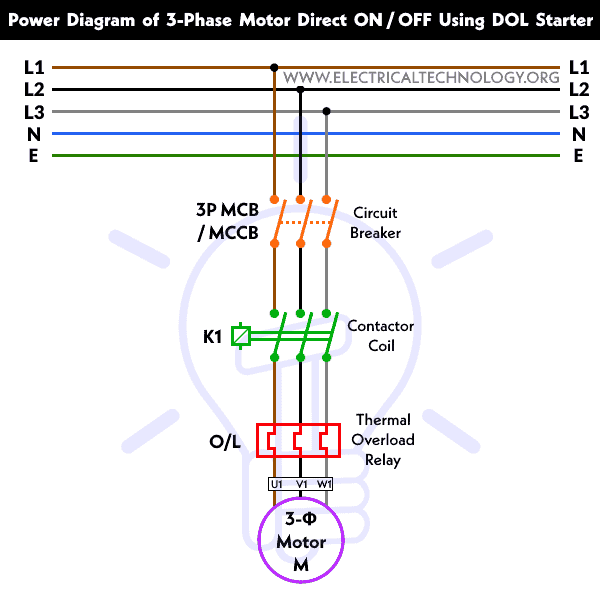
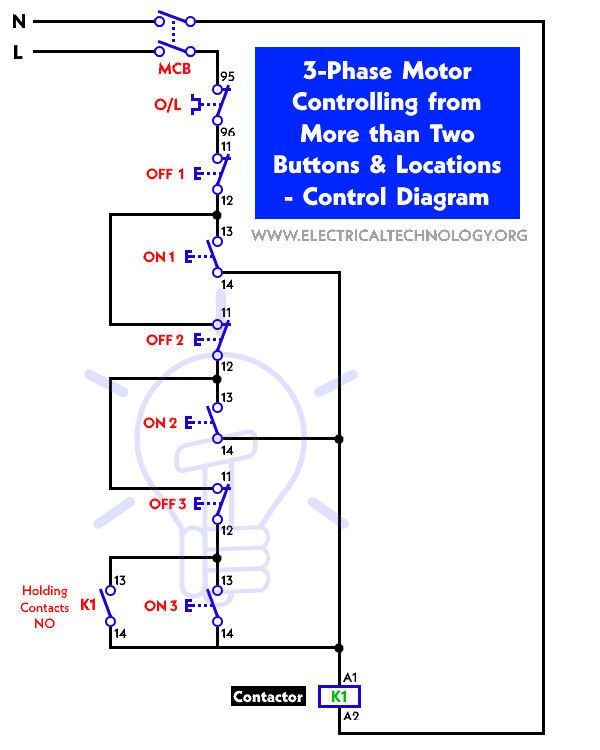
The following wiring diagrams show the controlling of a 3-Phase motor from different places using DOL starter and pushbuttons.
Power Diagram
Control Circuit Diagram
Challenges of Multi-Button Motor Control
Controlling a 3-phase motor from more than two buttons introduces several challenges:
- Interlocking: To prevent conflicting commands from multiple buttons, an interlocking mechanism must be in place. This ensures that only one command (start or stop) is executed at a time. This prevent the damage to the motor or machinery.
- Complexity: As the number of control buttons increases, so does the complexity of the control system. Design and wiring can become intricate.
- Distance: The control stations may be located far apart, making it impractical to run wires directly from each station to the motor starter.
- Safety: Emergency stop functionality must be available at all control points to ensure the safety of personnel and equipment.
- Reliability: The control system must be reliable, ensuring that a command to start or stop the motor is always executed correctly.
Working of the Motor Control Circuit
Let’s see how the control circuit of a 3-phase motor can be operated from more than two locations using pushbuttons.
Multi-Button Control Stations
One straightforward approach is to install multi-button control stations at various locations within the facility. These stations are wired directly to the motor starter’s control circuit. Each station can include multiple buttons for different functions, such as start, stop, forward, reverse, and speed control.
In the above circuit, three ON (NO) and OFF (NC) pushbuttons are used. (Additional ON/OFF buttons may be added if you want to control the motor from even more places. An additional emergency stop buttons may be added for extra protection.)
As shown, when the operator presses the ON 1 switch, the holding circuit is completed since all the OFF pushbuttons are normally closed (NC). Consequently, the contactor energizes, and the motor starts running.
When the operator presses the OFF 1 switch, the entire circuit is interrupted because all the ON buttons are normally open (NO). Thus, the holding circuit releases its contacts, and the motor stops.
This same process applies to all pushbuttons, whether they are ON or OFF.
Advantages:
- Simple and direct control.
- Clear user interface with labeled buttons.
- Suitable for applications with a limited number of control points.
Disadvantages:
- Complex wiring if many buttons are required.
- May not provide advanced features like remote control or automation.
Related Posts:
- ON / OFF Control of a 3-Phase Motor Using a DOL Starter
- ON / OFF 3- Phase Motor Using 8-PIN Relay and DOL Starter
- ON / OFF 3- Phase Motor Using 14-PIN Relay and DOL Starter
- ON / OFF 3- Phase Motor Using 11-PIN Relay and DOL Starter
- Auto & Manual Control of 3-Phase Motor using DOL & Digital Timer
- Reverse-Forward of 3-Phase Motor using DOL Starter
- Auto & Manual Control of 3-Φ Pump Motor using Float Switch
- Automatic & Manual Control of 3-Phase Motor Using Delay Timer
- Automatic ON/OFF Circuit Using Two 8-PIN Timers for 1 & 3-Φ Load
- How to Control a Three-Phase Motor Using a Foot Pedal Switch?
- Compressor Motor Control in Refrigeration Using Soft Starter
- Even More Power & Control Wiring Diagrams


Dear sir,
Excellent work, i want to know about the relay diagram 12vdc and 220vac
Dear sir, I really appreciate the wiring, it’s quite easily to understand. I needs more of it to know, like water pomp motor.
I have to take exception with your control diagram.
The OFF push buttons should be shown normally closed.
The diagram above indicates that they are normally open resulting in the motor never starting.
This is a very useful sit for we electrical guys
Hi
I am looking for circuit diagram to control a small lift (elevator) from two places with the three buttons on each location (down button, up button and stop button) for 220v motor. I wonder if you can help me with this circuit design.
thanks
Can’t understand how the holding contact would prevent the coil from going off.