Power System MCQs with Explanatory Answers
Power System MCQs with Explanatory Answers
(Generation, Transmission and Distribution MCQs with Explanatory Answers )
1. Volume of The Conductor is inversely proportional to the ____________.
- Voltage (V)
- Half of the Voltage (½ V)
- Squire of the Voltage (V2)
- None of the above
Show Explanatory Answer
Explanation:
Power in Three Phase Circuits P = √3 V I Cosθ OR I = P / √3 V Cos θ (1)
Law’s of resistance = R = ρ (l /A) (2)
Power Loss in Three Phase Circuits = P = 3 I2R (3)
Putting the Values of I and R from Equation (1) and (2) into Equation (3).
P = 3 (P / √3 V Cos θ)2 x [ρ (l /A)]
P = 3 (P2/3 V2 Cos2 θ) x ρ (l /A)
P = W = P2 ρ l/ V Cos2 θ A… OR … A = P2 ρ l/ V2 Cos2 θ W (4)
Volumeof the conductor in Three Phase System= Vol = 3A x Length (5)
Putting the value of “A” from Equation (4) into Equation (5)
Vol = 3 P2 ρ l/ W V2 Cos2 θ x l
Vol = 3 P2 ρ l2/ W V2 Cos2 θ
Hence Proved that Volume of the Conductor is inversely proportional to squire of Voltage
Volume of the Conductor = Vol ∞ 1/V2
2. Which among these is not a conventional source of electrical energy?
- Wind
- Gas
- Coal
- Diesel
Answer: ( 1 )
Show Explanatory Answer
Wind is a non-conventional source of energy. With increasing price of oil, depletion of fossils and other environmental degradations, renewable sources of energy is being more preferred. Wind energy is generated using Windmills located mostly near to coastal and remote areas.
3. General output power from Wind energy ranges from——-
- 20kW to 12MW
- 30kW to 5MW
- 20kW to 2MW
- 10kW to 10MW
Show Explanatory Answer
Answer: ( 2 )
Developed power or output power of a Windmill is given as:
Where, A is area swept by the windmill
d is wind density of air, and
v is wind velocity
Generated electric power ranges from 30kW for individual units to 5 Mega Watts for multiple units, with the hub height being 80 meters and rotor diameters being 65 meters.
4. Typical value of Solar constant is:
- 1400 kCal/m2-h
- 1200 kCal/m2-h
- 1500 kCal/m2-h
- 2000 kCal/m2-h
Show Explanatory Answer
Answer: ( 2 )
Rate at which solar energy reaches the earth’s atmosphere is known as Solar constant. Solar power, falling upon the earth is of the magnitude of 1.7 x 10¹⁴ kW. Value of solar constant is 1200 kCal/m2-h or 1.39 kWH/m2-h.
5. The widely-used fuel in thermal power plants is:
- Coal
- Natural Gas
Show Explanatory Answer
Answer: ( 1 )
Coal is the widely-used fuel in thermal power plants due to two important factors – availability and low cost. In India, the domestic coal production has increased about 6 to 8% annually since the last 30 years.
6. For a power system, the demand factor lies between: —
- 2 to 0.5
- 5 to 0.8
- 4 to 1.0
- 5 to 1.0
Show Explanatory Answer
Answer: ( 2 )
Demand Factor is defined as the ratio of maximum demand to the connected load. Maximum demand is the maximum power drawn by the circuit at any time. It also refers to the maximum demand occurred during a day, month or year. Ideally maximum power is equal to connected load if each electric device is operated simultaneously, which is a hypothetical situation. Hence maximum demand is always less than the connected load and Demand Factor lies between 0.5 to 0.8.
7. Power Factor for anelectric supply system should always be equal to or close to unity.
- True
- False
Show Explanatory Answer
Answer: ( 1 )
Cosine of the phase difference between voltage and current, in a AC circuit, is known as power factor. It is defined as the ratio of real power to apparent or reactive power. It should always be close to or equal to unity because low power factor leads to high cost of poor voltage regulation, huge energy loss in conductors and increasing cost of electric station and distribution equipment.
8. Low power factor is caused due to——-
- Use of transformers and inductive loads
- Use of arc lamps and furnaces
- None of the above
- A and c
Show Explanatory Answer
Answer: ( 4 )
Power Factor is lowered due to various factors like use of transformers and other inductive loads, use of arc lamps etc. Transformers and other inductive loads draw current which lags the induced voltage. This causes huge amount of current to be drawn as the reactive power increases and the power factor decreases.
Also arc lamps and furnaces operate at low power factor due to their varying nature and characteristics.
9. Modern overhead transmission lines use ACSR conductors for both distribution and transmission—–
- True
- False
Show Explanatory Answer
Answer: a
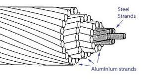
ACSR conductors stands for Aluminium Conductor Steel Reinforced.
Figure 1: Aluminium Conductor Steel Reinforced
These are most commonly used conductors in transmission and distribution lines because of their low cost with good efficiency and durability, high mechanical strength, low corona loss and low skin effect.
10. For a three phase, 10 km long transmission line with resistance of 0.8Ohms/km and inductance of 1.2mH/km and power factor of 0.7, if receiving end voltage is 40kV and sending end voltage is 42kV, 50Hz, the value of line current, regulation and efficiency of the transmission line are——————-respectively.
- 15 Amperes, 5%, 93%
- 14 Ka, 4.744%, 93.5%
- 12Ka, 5%, 94%
- 15Ka, 2%, 95%
Show Explanatory Answer
Answer: ( 2 )
Given:
Length of transmission line = 10 km
Total resistance = 8 Ohms
Total inductance = 12 mH
Thus reactance, X = 2πfL = 3.77 Ohms
Power Factor, cosφ = 0.7
Thus, sinφ = 0.71
Receiving end line voltage, Vrel = 40kV
Therefore, Receiving end phase voltage, Vreph = Vrel/31/2 = 23.09kV
Sending end line voltage, Vsel = 42kV
Thus, Sending end phase voltage, Vseph = Vsel/31/2 = 24.24kV
From the phasor diagram below, the following equation can be written
Substituting the values, we get
587.57 = 533.15 + 258.6Ire + 123.61Ire + 30.21I2re
Or, 54.42 = 382.21Ire + 30.21I2re
Solving the above equation and ignoring the negative value, we get line current, Ire = 0.14kA
Efficiency = Power Output / ( Output + Losses )
Power Output, P = 3Vreph x Ireph x cosφ = 6.78MW
Losses = 3Ire2R = 0.47MW
Thus, Efficiency = 93.5%
11. For a single core cable with a conductor of diameter 5 cm and lead sheath diameter of 8 cm, designed for anoperating voltage of 35kV, the maximum and minimum values of electric stress, ——respectively.
- 30 kV/cm, 19 kV/cm
- 78 kV/cm, 18.61 kV/cm
- 31 kV/cm, 19 kV/cm
- 42 kV/cm, 20 kV/cm
Show Explanatory Answer
12. High Voltage DC (HVDC) transmission is preferred over High Voltage AC transmission for long distance power transfer.
- True
- False
Show Explanatory Answer
Answer: ( 1 )
High Voltage DC transmission is preferred over High Voltage AC transmission because of the following limitations imposed on the transfer of power:
- Stability: The power flow from one end of the line to other end depends upon the line reactance, difference between voltage angles and magnitudes of voltages. At transient power flow, the difference between voltage angles is small, beyond which the system becomes instable.
- Current carrying capacity: Use of cables in AC transmission increases the chance of building up of high current due to presence of capacitance. This makes it impossible to use cables for longer distance, more than the critical length (length at which charging current is equal to its thermal limit).
- Reactive Power Loss: Reactive power loss is predominant in AC transmission due to presence of line inductance and capacitance.
13. Power is transmitted over transmission lines on high voltage because——
- Conductor cost is reduced
- Current is reduced
- Efficiency is increased
- A and C
Show Explanatory Answer
Answer: ( 4 )
Consider the below parameters for a transmission system
V – Line to Neutral Voltage
I – Line current
Φ – Phase angle between voltage and current
Resistance of each conductor per phase – R
Power transmitted per phase, P = VIcosφ
Power loss in each conductor due to flow of current,
Above equation proves that power loss will be minimum at high voltage and high power factor.
Also for area of cross section a, length l and resistivity ρ, the resistance R = ρl/a
Above equation shows that for higher value of voltage, volume of conductor is less, which in turn saves cost of the conductor.
Efficiency,
Thus, for higher value of voltage and power factor, the efficiency will be higher.




Dear If we will put the value of equation (4) into (5) there should be Length^2 even there is no change in the result as this A = P2 ρ l/ V2 Cos2 θ W (4)<br />Volume of the conductor in Three Phase System= Vol = 3A x Length <br /><br />Vol = 3 P2 ρ l^2/ W V2 Cos2 θ
keep it up!