How to Measure Earth Loop Resistance Using Ammeter and Voltmeter?
How to Measure Earth Loop Impedance Using Ammeter and Voltmeter?
Purpose of measuring earth loop resistance is essentially to determine the resistance of the path through which current flows towards the earth in the event of a short circuit, or to find the resistance of the earth continuity conductor. This is done so that the circuit protective device, such as a circuit breaker or fuse, can act immediately and decisively in the event of a short circuit.
It is crucial to note that as the earth loop impedance decreases, the value of fault current increases, causing the circuit breaker or fuse to act more promptly. If the earth loop resistance is high, the circuit breaker or fuse may not open quickly during a fault due to the lower fault current flow. This could lead to hazardous situations. Therefore, it is essential to measure the earth loop resistance value using this test so that the operation of the circuit breaker or fuse in the event of a fault can be ensured.
This test can be conducted using an earth loop resistance tester, megger, digital ground/earth resistance tester or with the use of a voltmeter and ammeter.
In this tutorial, we will be using an voltmeter and ammeter to measure and calculate the earth loop resistance for specific circuit(s). It is important to ensure that the value of the current flowing through the earth loop is not more than 1.5 times the current rating of the circuit.
Before conducting this test, it is necessary to perform the insulation resistance test between the neutral and earth to ensure that the neutral is properly insulated from the earth.
Related Posts:
- How to Test Grounding / Earthing System using a Multimeter?
- How to Test Earthing – Grounding System using a Light Bulb?
Measuring Earth Loop Resistance using Ammeter and Voltmeter
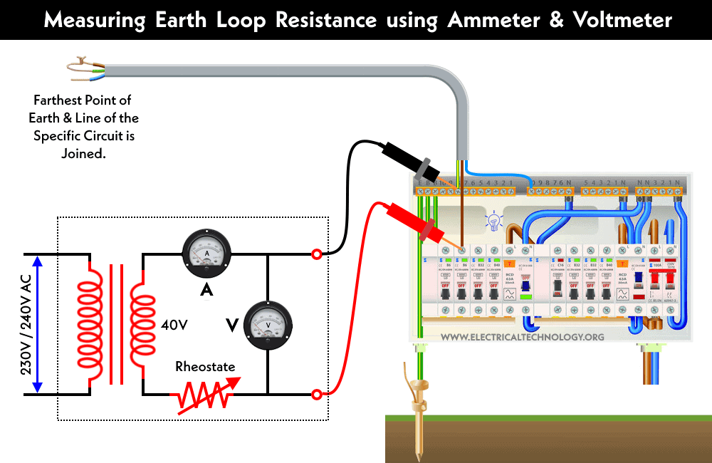
To measure the earth loop resistance, one cable of the circuit is used as the return path (utilized as the return path for fault current) and connected to the farthest point of the earth continuity conductor. The procedure for measuring earth loop impedance using an ammeter and voltmeter is demonstrated in the following fig.
The maximum voltage from the transformer secondary windings is 40 volts. The testing leads coming out of the secondary side of the transformer are connected to the termination point of the cable and bonded to the ground rod / earth electrode (as shown in the diagram).
This completes the circuit, and the current flows through the continuity conductor. The value of this current is adjusted to 1.5 times the circuit current rating through a rheostat so that the current does not exceed 25 amperes.
For example, if the circuit current rating is 10 amperes, the transformer supplies 15 amperes to the circuit. Afterward, the voltmeter and ammeter readings are noted, and the total earth loop resistance value is determined using Ohm’s law formula.
Total Loop Resistance = Voltage ÷ Current
= Reading of Voltmeter ÷ Reading of Ammeter
RL = V ÷ I
Since the resistance of the wiring cable used as the return path is included in the total value of this resistance, the resistance of the wiring cable should be subtracted from the total resistance value to determine the actual resistance value of the earth continuity conductor. The resistance of a specific cable and wire, determined by its length and size, can be found by using the resistance tables for the cable’s conductors.
Earth Loop Resistance = Total Loop Resistance − Resistance of Wiring Cable
The value of earth loop resistance should not be more than one ohm (1-Ω) in the case of a copper conductor and not more than half an ohm (0.5Ω) in the case of a steel conduit.
Related Posts:
- How to Measure Ground Resistance? – Testing Earth Resistance
- How to Test the Earth Fault Loop Impedance – Various Methods
- How to Measure Resistivity of Earth Using Wenner Method?
- How to Test and Measure the Ground Resistance using a Megger?
- How to Size the Earth Conductor, Earthing Lead & Earth Electrodes?
- Protective Multiple Earthing (PME) – TN-C-S – (MEN) and PNB
- Design of Grounding / Earthing System in a Substation Grid
- Why are Salt and Charcoal Added in Earthing Pit for Grounding?
- What is the Purpose of Ground Wire in Overhead Transmission Lines?
- Difference Between Grounding, Earthing and Bonding
- What is the Difference Between Neutral, Ground and Earth?
- Difference Between Real Ground and Virtual Ground
- Why is the Grounding Wire Bare and Not Insulated?
- What is Ground Rod and How to Install a Ground Electrode in Grounding System?
- Why is Copper Rod Used as Ground Rod in Grounding / Earthing System?
- Electrical Earthing and Grounding – Methods, Types and Installation
- What is Ground Resistance Tester – Working of Ground or Earth Tester


