Inductor Symbols -Solenoid, Chock and Coils Symbols
Inductor Symbols – Coils and Choke Symbols
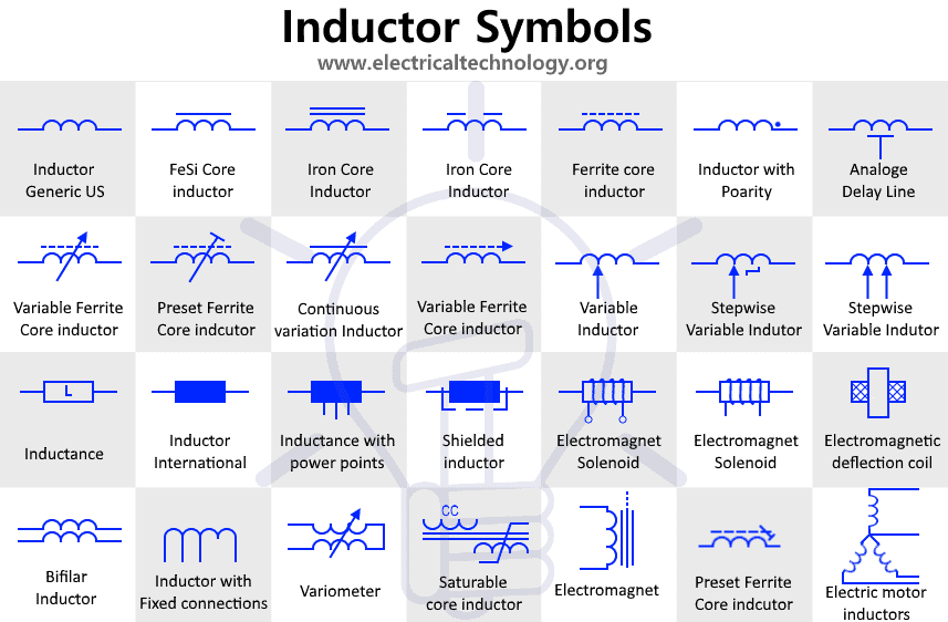
This is the symbols used for representing a generic Inductor whose inductance value is fixed. An inductor is also known by many names such as coil , choke etc. stores energy inside magnetic field.
This type of inductor has variable inductance. Its inductance can be changed during the operation of the circuit such as in radios.
The inductance of such variable inductor can be varied in steps rather than in a continuous manner. They have designed (fixed) value of resistance per step.
Such inductors have a dot on one side of its terminal. The dot convention of the inductor shows the direction of the current entering the inductor & they are used while coupling inductors for maximum mutual inductance.
This is a type of inductor whose core is made up of iron (Ferromagnetic material). The iron core increases the inductance of the inductor due to its high magnetic permeability.
As the name suggests, these inductors have ferrite core. The ferrite material provide high magnetic permeability as well as low electrical conductivity to reduce the losses inside the core. They are used in high frequency applications.
Variable Ferrite Core Inductor
It is a type of ferrite core that has variable inductance. The inductance of such inductors is varied by screwing in & out the core inside the coil.
The preset inductors are also variable inductor but there inductance is varied at the time of manufacturing or tuning a circuit. Their inductance is not changed during normal use of the circuit.
Such type of inductors core is designed to contain its magnetic field inside. There is little to know leakage flux that could interfere with other nearby components. These are used in compact PCBs where space managing is the utmost requirement.
A solenoid is a cylindrical coil made of a conductor which produces magnetic field when electricity passes through it. It is also known as Electromagnet.
Electromagnetic Deflection Coil
Such type of coil is used in CRT (cathode ray tube) where it produces the magnetic field to deflect or change direction of the electron beam both vertically and horizontally.
The coil of bifilar inductor is made up of two conductors running in parallel with each other. The winding conductors can be antiparallel (reverse direction of current) to cancel the magnetic field produced by each other. They can be in parallel to double fold the magnetic field produced by the coil.
The variometer is a variable inductor that provide a continuous change in inductance by moving the two coils inside one another that are connected in series.
This type of inductor is deliberately designed to saturate its core to decrease its inductance & inductive reactance. This results in high AC current carrying capability.
It is the graphical representation of the coil (winding) used inside AC machines which converts the electrical energy into mechanical energy through induction.
It is a coil designed to produce a time delay or phase change in the analog signal. Just like digital buffers are used to produce time delay in digital signal.
Related Electrical and Electronic Symbols:
- Basic Electrical and Electronic Symbols
- Transformer Symbols
- Motors Symbols
- Generator and Alternator Symbols
- Resistor Symbols
- Capacitor Symbols
- Fuse and Circuit Breaker Symbols
- Switch and Push Button Symbols
- Relay Symbols
- Diode Symbols
- Transistor, MOSFET and IGFET Symbols
- Thyristor, DIAC and TRIAC Symbols
- Electronic Logic Circuits and Programming Symbols
- Digital Logic Gates Symbols
- Digital Flip-Flop and Latches Symbols
- Electronic Filters Symbols


