What is Inductor – Its Working, Parameters, Factors & Applications
Inductor and its Working, Parameters, Factors and Applications
An inductor is one of the most used electrical components in a circuit. It is referred by many names such as choke, coil or reactor.
Inductor:
An inductor is a two terminal passive electrical component that store energy in a magnetic field. This magnetic field is produced due to the current flow through it.
It is basically made up of a coil surrounding a core. Every coil is an inductor essentially. The change of current through the coil produces a magnetic field around it. This magnetic field, according to Lenz’s law, induces an EMF across the coil that is opposite in direction to the input current. Thus an inductor opposes any change in supply current.
- Related Post: What is a Solenoid and Solenoid Magnetic Field
Inductance:
Inductance is the ability or property of inductor to produce an electromotive force (EMF or voltage) due to change in the electric current.
It is the ratio of the voltage to the rate of change of current through the inductor.
L = V / (di/dt)
The SI unit of inductance is Henry named after American scientist Joseph Henry. Its equivalent is Weber/Ampere.
1 Henry is the amount of inductance when a current change of 1 ampere per second in a coil produces an EMF of 1 volt. It is denoted by H.
The inductance of an inductor depends on many factors discussed in brief down below. Inductors have inductance typically ranging from 1μH up to 20H.
- Related Post: Inductance of Air Core Inductor Calculator
Symbol of Inductor:
There are different types of inductors. They are denoted with various symbols in a circuit’s schematic. Symbols of some of the inductors are given below:
Working of Inductor:
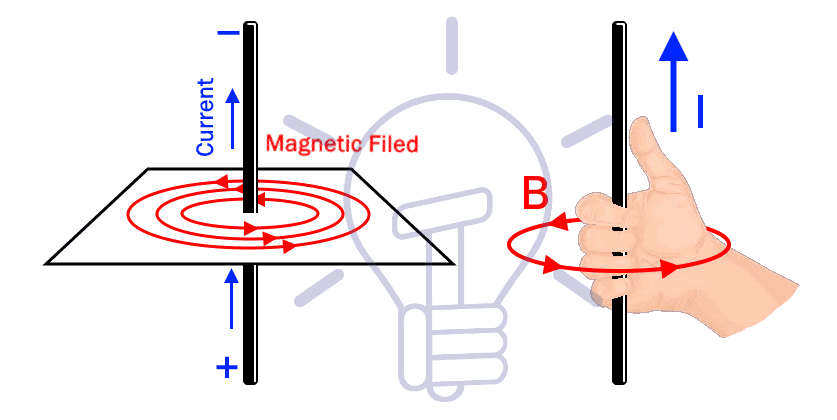
According to the electromagnetism rule, Oersted’s law, when a steady current is passing through a straight conductor, it produces a magnetic field around it. The strength of the magnetic field depends on the supply current. If the current through the conductor is changed, the resulting magnetic field will also change. This magnetic field produced is perpendicular to the conductor.
The direction of the magnetic field produced can be found using the Fleming’s right hand rule or the right-hand grip rule. Curl your finger as if you are holding the conductor & point your thumb in the direction of the current. The thumb shows the direction of the current whereas the curly fingers show the direction of the magnetic field around the conductor.
As we know that an inductor is a conductor wrapped in the form of a coil. A varying magnetic field is produced by varying the current passing through it. The changing magnetic field causes the magnetic lines to cut across some of the conductor, which induces an EMF in the wires. This phenomenon is known as Self-Induction.
According to Lenz’s, this EMF induced in the coil is opposite in direction to the supply current & opposes any change in the supply current. The higher the rate of change of supply current, higher the rate of change of magnetic field & stronger the opposing induced current.
In simple words, the reactance (resistance) of the inductor increases with an increase in the supply frequency. It increases to the point where it completely blocks the input current. So an inductor blocks AC current while it behaves as a shorts circuit for DC current.
- Related Post: Parallel Inductor Calculator
Parameters of Inductor:
The parameters of any electronics component define its performance & usage. It provides us the knowledge of how & in what kind of circuit these components should be used. Some of the parameters of an inductor are given below:
DC Resistance (DCR):
The resistance of an inductor for a Direct Current is called DC resistance.
Ideally, an inductor should not have any DC resistance (DCR) but it tends to have some resistance at or near 0Hz signals. In a circuit, it is simulated as a separate series resistance with an inductor.
To measure DC resistance of an inductor, apply DC voltage and measure the current through it. Then calculate the Resistance using Ohm’s law for the given voltage & current.
RDC = V/I
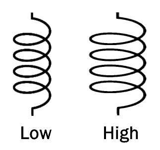
It is usually around a few ohms. The DC resistance of an inductor depends on the length, cross-sectional area of the wire used. It is lower for low-value inductors, while higher for the high-value inductor.
- Related Post: What is Resistor and their Applications
Saturation Current:
Basically, increasing the current through a coil wrapped around a ferromagnetic core increases it flux produced in it. At a certain point, the core becomes completely saturated & increasing the current won’t increase the flux in the core. So the current at which the core becomes saturated is known as saturation current of the inductor.
Exceeding the saturation current decreases the permeability of the core. This subsequently results in a drastic decrease in the inductance of the inductor. The reduction in the inductance at the saturation current is between 10 to 20%.
Remember, only ferromagnetic materials can have magnetic flux inside them. So an air core inductor does not have any saturation current.
Rated Current:
It is the maximum rating of current that the wire used in the winding of the inductor can tolerate at a specific temperature. The inductor can safely operate at this rated current without damaging the winding.
Exceeding the rated current of the inductor will thermally damage the insulation of the windings, causing shorted turns (which will eventually destroy the whole device).
The steady current through the inductor should not exceed the rated current of the inductor.
- Related Post: What is a Capacitor and their Applications
Core Permeability:
The permeability of the core plays a vital role in the inductance of the inductor. Increasing the permeability of the core increases the inductance. The size, shape & the material used in the core effects the inductance.
Self-Capacitance:
As we know, there are multiple turns in the coil of an inductor. In between each of these turns, there is a capacitance because the turns are at close proximity & at a different potential (only in AC, because in DC the winding is short).
By increasing the frequency, the inductive reactance increases & capacitive reactance decreases. Due to which the inductor operate as a capacitor.
To reduce self-capacitance, the turns in the winding of high-frequency inductors are kept far apart.
- Related Post: What is a Diode and Their Applications
Self-Resonant Frequency:
As we have established that there is a capacitance between the turns of the coil. This capacitance creates a parallel LC circuit.
By increasing the frequency there comes a point where the inductive reactance equals the capacitive reactance. This frequency is known as the resonant frequency.
The inductor has very high impedance at the resonant frequency & appears as an open circuit.
Increasing the frequency above resonant frequency will decrease the capacitive reactance & the inductor will start behaving like a capacitor. To avoid this problem, the inductors are used below their self-resonant frequency.
Power Loss in Inductor:
Copper Loss
The loss that occurs due to the resistance of the winding of the inductor is referred to as copper loss. These losses depend on the current flowing through the inductor.
Copper Loss = I2R
Hysteresis Loss
The power loss due to the reversing magnetic field in the core is called hysteresis loss.
During the positive half cycle, the core magnetizes & saturates. During the negative half cycle, the core does not immediately demagnetize instead it wastes some power in the core.
Different core materials have different hysteresis coefficients. Low hysteresis coefficient materials have low hysteresis losses.
Eddy Current Loss
The current induced in the core of the inductor due to the magnetic field surrounding it is called eddy current. The losses due to this current are called eddy current loss.
This loss can be minimized by using a laminated core.
Factors Affecting the Inductance of Inductor:
Inductance is the result of the magnetic field due to the current per turn in the coil. There are 4 main factors that affect the inductance of the inductor. Each one of them is elaborated down below;
Length of Coil:
Assume all other factors remain unchanged, increasing the length of the coil decreases the inductance of the inductor.
Due to an increase in the length of the coil, there is more opposition to the magnetic field created by the current per turn.
- Related Post: Filters, Types of Filters and Their Applications
Cross-Sectional Area of Coil
Assuming all other factor remains unchanged, increasing the cross-sectional area of the coil increases the inductance of the inductor.
Because of increasing the cross-sectional area there is less opposition for the magnetic field produced.
Number of Turns
The magnetic field is produced due to the current flow in these turns, so increasing the number of turns will increase the total magnetic field. Thus it increases the inductance of the coil.
Permeability of Core:
The permeability of the core increases the magnetic field of the coil by a hundred folds. So having a core with high permeability increases the inductance of the same coil.
Types of Inductors
Here is the detailed post about different types of inductors like solenoid, chokes, fixed and variable inductors with their applications.
Applications of Inductor
Frequency Selective Circuits (Filters)
Inductor together with resistor & capacitor can be used in different frequency filter such as high pass, low pass, band pass & band reject filter.
They frequency filters are used in separating unnecessary frequency component from the signal.
Related Posts:
Tuning Circuit:
Inductor combined with the capacitor is used in the tuning circuit in radio & television etc. for selecting the desired frequency.
Sensor:
An inductor is used in sensors for detecting an object in proximity without any physical contact. The inductor as we know creates a magnetic field around it when current flow through it or any change in the magnetic field causes an induced current in the inductor.
Any metal object near an inductor will disrupt its magnetic field. The change in the magnetic field will cause a current in the inductor. Any change in the current can be detected by connecting it with the current sensing circuit. Thus we can detect any metal object using this technique.
Inductive proximity sensor & Induction-loop traffic sensor are most common inductive sensors used. Both of them are used for detecting object while the latter is used for detecting the amount of traffic at a busy intersection. The traffic data is used for efficient control of the signals.
Transformers
A transformer is essentially two separate inductors in close proximity with a common core that uses the magnetic flux created by one coil and induces EMF in the other coil through mutual induction.
Transformers are used for stepping up or stepping down of voltage in power transmission.
Electromagnetic Relay:
An electromagnetic relay is an electronic switch that has an inductive coil that creates a magnetic field when the coil is energized. This magnetic field pulls the terminal’s contact together allowing the current to flow.
Induction Motors
In the induction motor, the rotor rotates due to the rotating magnetic field produced by the winding across the stator. Its rotor speed depends on rotating magnetic field which depends on the supply frequency. So the only way to vary the speed is through the use of inductor.
Related Post:
- Faraday’s Law of Electromagnetic Induction
- Coulomb’s Laws of Magnetic Force – Formula & Solved Example
- Fleming’s Left Hand Rule and Fleming’s Right Hand Rule
- Basic Magnetic Terms definition with Formulas
- Maximum Flux Density (Bmax) Calculator. (Formulas & Equations)
- LVDT: Linear Variable Differential Transformer & Inductive Sensors


