What is Voltage Drop? Advanced Voltage Drop Calculator with Solved Examples
Advanced Voltage Drop Calculator with Solved Examples & Formulas
What is allowable Voltage Drop?
According to the NEC (National Electric Code) [210.19 A (1)] FPN number 4 and [215.2 A (3)] FPN number 2, the allowable Voltage drop for feeders is 3% and the acceptable voltage drop for final sub circuit and branch circuit is 5% for proper and efficient operation.
For example, if the Supply voltage is 110V, then the value of allowable voltage drop should be;
Allowable Voltage Drop = 110 x (3/100) = 3.3V.
We have already discussed the selection of proper size of cable for electrical wiring installation in SI and British system with examples.In the above article, we have also explained the voltage drop calculation and voltage drop formula as well as online cable size calculator.
Today, we are going to share an Online Advanced Voltage Drop Calculator and Voltage Drop formulas in detail with solved examples.
Good to know: Read the full description below the voltage drop calculator for better explanation as there are many voltage drop calculation formulas with example. in addition, there is also a very simple method to calculate the voltage drop.
Also check
Voltage Drop Calculator (Advanced)
Note: This Calculator is also available in our Free Electrical Technology Android App
- More related Electrical & Electronics Engineering Calculators
Voltage Drop Formulas and Calculation
Basic Voltage Drop Formula.
The basic electrical Voltage drop formula is;
VD = IR ……. (Ohm’s Law).
Where;
- VD = Voltage Drop in Volts.
- I = Current in Amperes.
- R = Resistance in Ohms (Ω).
But this is not always the case, and we can’t run the wheel of the system with this basic formula (Why? See below cases as well).
Voltage Drop Formula for Steel Conduit.
This is the approximate voltage drop formula at unity power factor, cabal temperature 75˚C, and cable conductors in steel conduit.
VD = (2 x k x Q x I x D) / cm for Single Phase.
VD = (1.732 x k x Q x I x D) / cm for Three Phase.
Where;
- Cm = the cross sectional area of the conductor in circular mils.
- D = the one way distance in feet.
- I = the circuit current in amperes.
- Q = the ratio of AC resistance and DC resistance (RAC/R/DC) for conductor larger than 2/0 for skin effect.
- k = specific resistivity = 21.2 for Aluminum and 12.9 for Copper.
Voltage Drop formula for Single Phase and DC Circuits
When wire length is in feet.
VD= I × R
VD = I × (2 × L × R / 1000)
Where ;
- VD = Voltage Drop in Volts.
- I = Wire Current in Amperes.
- R = Wire Resistance in Ohms (Ω) [Ω/kft].
- L = wire distance in feet.
And;
When Wire length is in meters.
VD = I × (2 × L × R / 1000)
Where;
- VD = Voltage Drop in Volts.
- I = Wire Current in Amperes.
- R = Wire Resistance in Ohms (Ω) [Ω/km].
- L = wire distance in meters.
Voltage Drop Calculation and Formulas for Three Phase system.
-
For 3 Phase 3 Wire system. (Delta Connection)
VD = 0.866 × I × R
VD = 0.866 × I × 2 × L× R/ 1000
-
For 3 Phase 4 Wire systems. (Star Connection)
VD = 0.5 × I × R
VD = 0.5 × I × 2 × L× R/ 1000
Where;
- VD = Voltage Drop in Volts.
- I = Wire Current in Amperes.
- R = Wire Resistance in Ohms (Ω) [Ω/km or] or (Ω/kft).
- L = wire distance in meters or feet.
Wire cross sectional area calculations
Wire cross sectional area in kcmil (kilo circular mils)
An = 1000×dn2 = 0.025 × 92(36-n)/19.5
Where;
- An = cross sectional area of “n” gauge wire size in kcmil.
- kcmil = kilo circular mils.
- n = the number of gauge size.
- d = wire square diameter in in2.
Wire cross sectional area in square inches (in2).
An = (π/4)×dn2 = 0.000019635 × 92(36–n)/19.5
Where;
- An = cross sectional area of “n” gauge wire size in square inches (in2).
- n = the number of gauge size.
- d = wire square diameter in in2.
Wire cross sectional area in kcmil (kilo circular mils)
An = (π/4) ×dn2 = 0.012668 × 92(36-n)/19.5
Where;
- An = cross sectional area of “n” gauge wire size in square millimeters (mm2)
- n = the number of gauge size.
- d = wire square diameter in mm2.
You may also read: How To Locate Faults In Cables? Cable Faults, Types & Causes
Wire diameter Calculation
-
Wire diameter in Inches formula
dn = 0.005 × 92(36-n)/39 …. In inches
Where “n” is number of the gauge size and “d” the wire diameter in inches.
-
Wire diameter in mm (millimeters) formula
dn = 0.127 × 92(36-n)/39 …. In millimeters (mm).
Where “n” is number of the gauge size and “d” the wire diameter in mm.
Wire Resistance calculations formula
(1). Rn = 0.3048 × 10⁹ × ρ / (25.42 × An)
Where;
- R = Resistance of the wire conductors (in Ω/kft).
- n = # of Gauge size.
- ρ = rho = resistivity in (Ω·m).
- An = the cross sectional area of n #gauge in square inches (in2).
Or;
(2). Rn = 109 × ρ/ An
Where;
- R = Resistance of the wire conductors (in Ω/km).
- n = # of Gauge size.
- ρ = rho = resistivity in (Ω·m).
- An = the cross sectional area of n #gauge in square millimeters (mm2).
Voltage Drop at the End of the cable formula and calculation.
VEnd = V – VD
Where;
- VEnd = Supply voltage at the end of the cable.
- V = Supply voltage.
- VD = Voltage Drop in the cable conductors.
Voltage Drop Calculation formula for Circular mils
VD = ρ P L I / A
Where;
- VD = Voltage drop in volts.
- ρ = rho = specific resistivity in (Ω – circular mils/foot).
- P = Phase Constant = 2 (for single phase and DC system) and = √3 = 1.732 (for three phase system)
- L = wire length in feet.
- A = wire area in circular mils.
How to calculate voltage drop in copper conductor (1 & 3 phase)?
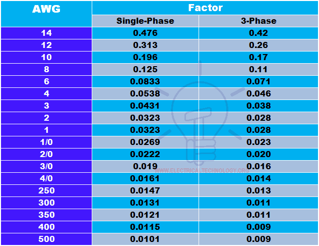
The voltage drop in copper conductors can be calculated via the below simple and easy formula with the help of the following table.
VD = f x I … L = 100 feet
Where;
- f = factor from the table below.
- I = Current in amperes.
- L = conductor length in feet (100 feet).
(See the solved example below the table for clear understanding)

Solved Example on Voltage Drop Calculations
Example: Suppose, Voltage is 220V single phase, current is 5A, Conductor length is 100 feet, and Wire gauge (AWG) is #8. Calculate the voltage drop?
Solution:
The voltage drop can be found by the following formula
VD = f x I … L = 100 feet
Since the factor for #8 AWG conductor is 0.125 (from the above table). Now, putting the values in the above formula.
VD = 0.125 x 5A x ( for 100 feet)
VD = Voltage drop = 0.625V.
P.S: The above voltage drop calculator provides approximate values and we do not guarantee of 100% accurate results as results may change with different and real cables, conductors, wires and different resistivity of material, number of strands in wire, temperature and weather condition, conduit and PVC etc.
Related Posts:
- How to Find The Proper Size of Cable & Wire ? Examples in British and SI System
- Cable Size Calculation for LT & HT Motors
- How to Find the Size of Earth Conductor, Earthing Lead & Earth Electrodes?
- How to Find Voltage & Ampere Rating of Switch, Plug, Outlet & Receptacle
- How to Find the Proper Size of Circuit Breaker? Breaker Calculator & Examples


Really great detailed post, thanks for that!
thank you very muh
Update any new formula please informed me on my e – mail Id
thank you very much
The voltage drop formula must include the reactance impedance as well. Too many design software programs omit voltage drop and other safety code requirements, resulting in design deficiencies and fiascos like the Apollo 13 disaster. Contractors make multiple profits over eir original bid with change orders.
In your great calculator program, do I enter the cable length (the actual distance) or the total wire length (there and back)?
Can you please provide a reference from where are the formulas developed ??
bus duct system manufacturer providing the following characteristics in th catalogue
rating(amp) conductor(mm) impedence
2500 6×230 R 1.97 x 0.74 z 2.10
units in 10^-3
calculate the voltage drop of 2500A busbar used to supply 8floors.Each floor having 135kw load and total length of bus bar is 325 feet………….plz solve this question
It appears that the TEMPERATURE option is not taking effect on the RESISTANCE output value.
For example, setting input as 20C, Copper, 16 AWG, 150 ft, DC, 12V, 3.5A calculates to 4.2062 V, 35.0520 %, 1.2018 ohms, 7.7938 Ve. However, changing the temperature setting to 65C and pressing Calculate now shows 4.9634 V, 41.3614 %, 1.2018 ohms, 7.0366 Ve. Shouldn’t the resistance have changed as well as the other values?
Can anyone confirm? Can the calculator be fixed if so? (Or am I wrong?) Thank you!
Thanks a lot. This was very beneficial as I was going to use wrong wire gauge in my landscape project. I have not never had the though that 12v circuit will run 10 times AMP current that would be run in 110v circuit.
Great Post.
I would like to know what is the reason behind different voltage drop for 3phase 3 wire system and 3 phase 4 wire system ?
ENTES DIN rail mount timer Operating voltage: 230 V AC DTR-20 2 change-overs 16 A 250 V AC Astronomical
DTR-20 astronomic timer. This astronomic timer relay have it’s LED screen program setting not displayed in English language. Kindly assist with programming manual for timer relay
Super sir