Why Do We Need to Install a Starter with a Motor?
Why Do We Need to Connect a Starter with Electrical Motors?
Essential and Need of Starter with Motor
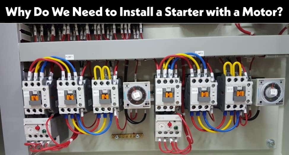
A starter is a device used in motors to start and accelerate. The function of a starter is to limit the starting current. At the time of starting the current flows through the motor is very high. The starter limits this current to a safe value.
Motors below 1 HP (0.746 Watts) are directly connected to the power supply without starter because their armature resistance is very high and they have the ability to afford and safely pass the higher current because of the high internal resistance. So the armature windings are safe and won’t be damaged from the high starting current while starting an electrical motor.
In the case of large motors, they have a very low armature resistance. If we connect these types of motors directly to the power supply (mostly 3-phase supply), then the higher amount of current will start to flow and it will destroy the armature winding due to low resistance at the initial starting stage while the motor is not running at normal position. The motor will not start to run at this stage because there is no back E.M.F in the motor. The back E.M.F of the motor is reached at full rate when the motor is running at full speed and rated load.
So this is the exact reason that’s why we connect a starter with a motor in series. A starter in series with the motor (i.e. resistance) reduces the high starting current as the armature needs low current due to rating at the initial stage and then runs at normal speed.
But this is not the end of the story. After starting the motor at low current, the starter resistance is reduced by turning the manual starter handle (the process can be automatic in case of automatic starter). This way, the rated current will start to flow through armature windings and the motor armature starts to rotate at full speed.
What is the Necessity of a Starter in AC and DC Motors?
When the DC motor is standstill, the speed of the rotor is zero. The back EMF is defined as;
Where,
- P = Number of poles
- ф = Flux per pole
- Z = Number of conductors
- A = Number of parallel paths
- N = Speed of rotor
Now, let’s consider the speed of the rotor is zero. Hence, from the above equation, the back EMF of the DC motor is zero. The current flows through the armature are defined as;
Here, in standstill condition, the back EMF is zero. So, the armature current is;
Where,
- V = Supply voltage
- Ra = Armature resistance
The value of armature resistance is very small. Generally, it is less than one ohm. Therefore, in this condition, a very large current flows through the DC motor, and this current is sufficient to damage brushes, commutators, and windings.
For example, consider a DC motor having an armature resistance of 0.8 ohms and is directly connected to the 240 V DC supply. Now find the armature current from the above equation.
Ia = V ÷ Ra = 240 ÷ 0.8 = 300 A
So, this current is 10-15 times of full load current. The armature winding is not designed to sustain this amount of current. Therefore, we need to reduce this current at a safe level and for that, a starter is connected in series with the armature winding.
When the motor is in running condition, the applied voltage (V) is opposed by the back EMF (Eb). Hence, the difference between both quantities is small. From the equation of armature current (eq-1), the value of armature current is small and under safe value during the running condition.
But in starting condition, the heavy inrush current may cause the following drawbacks;
- It causes heavy sparking at the commutators.
- It will damage the armature winding by temperature rise or by mechanical force set up by electromagnetic action.
- It will damage the rotating parts of the motor due to high starting torque and large acceleration.
Therefore, in starting period of the motor (5 to 10 sec), it is necessary to reduce the current to a safe level. Now, to reduce the starting current, we need to connect a high resistance in series with the armature winding. The extra resistance added to the motor must be removed gradually when the motor is in running condition and develops back emf.
When the motor reaches the rated speed, the additional resistance must be removed from the circuit. Otherwise, this resistance causes additional loss of energy and reduces the efficiency of the motor. Also, this additional resistance reduces the operating speed of the motor.
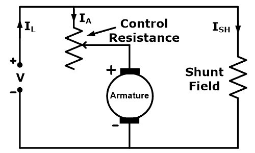
For example, we consider the simplest form of starter for DC shunt and compound wound motor. Variable resistance is connected in series with the armature winding as shown in the figure below.
At the time of starting the motor, the arm of the rheostat is placed at full resistance. Therefore, the entire resistance is connected in series with the armature winding. When the motor starts running, it develops back EMF that opposes the supply voltage. As the speed of a motor increases, move the arm towards the lower resistance. And when the motor reaches near the rated speed, the arm is placed at zero resistance. Therefore, in running conditions, there is no resistance added to the circuit.
In the above concept, it must include a few protective devices like no-volt release and over-load release. There are commonly two types of starters used for DC shunt and compound wound motor; Three-point starter and Four-point starter.
When the application needed a wide range of speed by shunt field motor, a four-point starter is used. And when no- (little) speed control is required, a three-point starter is used. Similarly, DOL and star-delta starter are used to run and operate the AC motors.
Related Posts:
- Three-Point Starter – Circuit and Working of 3-Point Starter
- Four-Point Starter – Circuit and Working of 4-Point Starter
What happens if we don’t connect a Starter with a Motor?
Let’s see the following example.
We know that the armature current can be found by the following formula.
Ia = V – Eb / Ra .…. ( I = V / R, Ohm’s Law)
Where,
- Ia = Armature current
- V = Supply voltage
- Eb = Back E.M.F
- Ra = Armature resistance
Related Post: Main Difference between Contactor and Starter
Suppose
A 5 HP (3.73 kilowatt) motor with 400 Volts having armature resistance of 0.25 ohms resistance and the normal full load current is 50 amperes. if we connect the motor directly to the power supply without starter, the result (of amount of flow of current) will be as follows:
Putting the values in the equation given above.
Ia = 400V – 0V / 0.25Ω
Ia = 1600 A
Ah! This high current will destroy the armature winding because it is 32 times higher than the normal full load current of the motor.
1600 A / 50 A = 32 Amps.
So that is the reason why we need to install a starter with a motor.
Related Posts:
- What is Motor Starter? Types of Motor Starters and Motor Starting Methods
- What is a Contactor ? Types, Working and Applications
- Direct Online Starter – DOL Starter Wiring Diagram for Motors
- What is Soft Starter? Its Working, Diagram and Applications
- Speed Control of DC Motor – Voltage, Rheostatic & Flux Control Methods
- Main Difference between Contactor and Starter
- Cable Size Calculation for LT and HT Motors
- Three Phase Motor Connection STAR/DELTA Without Timer – Power & Control Diagrams
- Three Phase Motor Connection Star/Delta (Y-Δ) Reverse / Forward with Timer – Power & Control Diagram
- Starting & Stopping of 3-Phase Motor from more than One Place Power & Control diagrams
- Three Phase Motor Power & Control Wiring Diagrams


thanx dear <br />bohat acha kam kar rahe ho.
Welcome and Thanks for appreciation.
Dear sir how work diesel engin of cummins kta50.if have vedio than share please.
Really. Thanks. Its totally easy to understand.
How can one calculate the suitable contactor for different selected motors that will operate effectively<br />
Why is it the a smaller motor has a higher armature resistance while a larger motor has a lower armature resistance?
thanks
.
What do you consider high currerentnt version low current
What do you consider a large Moyer to a small moteron
why do we connect motor in different ways. eg star-delta, delta-star.etc pls give d diagrams
please tell me how you get 0.25 ohm resistance
how we select different types of starters for motors
Been working with electronics for years, but your site has cleared up the fog over several issues.