Q Factor in Electrical and Electronics Engineering
What is the ‘Q’ factor in Electrical and Electronics Engineering?
Q Factor
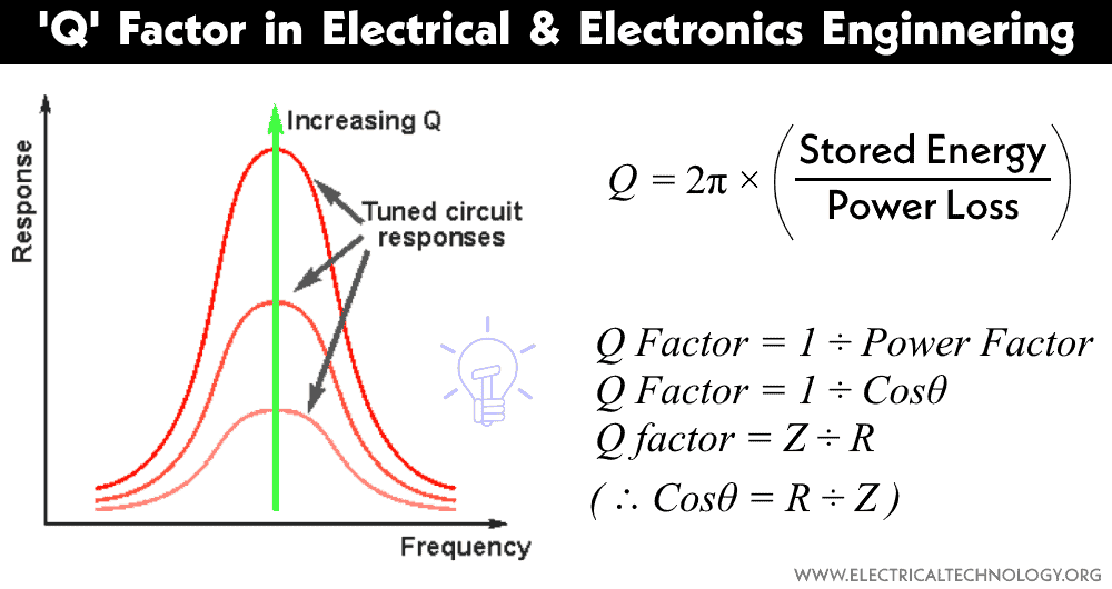
In a tuned circuit, the ratio between reactance and resistance is called the Q Factor or Quality Factor.
In other words, the opposite of the power factor is known as the Quality Factor ‘Q’ of a coil or its figure of merit.
Q Factor = 1 / Power Factor
= 1 / Cosθ = Z / R … (Where Power Factor Cosθ = R / Z)
If R is too small with respect to Reactance, then;
Quality factor = Z / R
= ωL / R = 2πfL / R … (ωL / R = 2πf)
Also, the Quality Factor (Q) may be defined as the ratio between stored energy and energy dissipated per cycle in a circuit: Mathematically, it is expressed as:
Q = 2π x (Stored Energy / Power Loss)
In a resonator, Q is the ratio between the stored energy in the resonator and the energy supplied by the generator to keep the signal amplitude constant:
Q = 2π (Maximum Energy Stored / Energy dissipate per Cycle), in the coil.
Quality factor is a parameter that characterizes the efficiency of a resonant circuit. It is commonly used to describe the behavior of circuits such as inductors and capacitors in AC circuits. It plays an important role in the design and analysis of various electrical and electronic systems, especially those involving resonance and frequency-selective circuits.
In electrical systems & circuits, the stored energy is the sum of the energies stored in lossless inductors and capacitors. The lost energy is the sum of the energies dissipated in resistors (heat, light, etc.) per cycle.
Whereas:
A capacitor absorbs reactive power and stores energy in the form of an electric field.
An inductor absorbs reactive power and stores energy in the form of a magnetic field.
And:
A resistor absorbs real power and dissipates it in the form of heat and light.
Q Factor in Pure Capacitive (C) and Pure Inductive (L) Circuits
As we know, the power in pure capacitive and inductive circuits is zero. Thus, the circuit power factor is also zero. However, the circuit ‘Q’ factor is the inverse of the power factor; thus, the ‘Q’ factor in both pure capacitive and inductive circuits is infinite (∞).
Q Factor in a Series RL Circuit
In a series RL circuit, Impedance (Z) = the inductive Reactance = XL = 2πfL, therefore the Quality factor “Q”
= Z / R → = XL / R → = 2πfrL / R
Q Factor in a Series RC Circuit
In a series RC circuit, Impedance (Z) = Capacitive Reactance = XC = 1/2πfC, thus, the Quality factor “Q”
= Z / R → = XC / R → = (1 / 2πfrC) / R → = 1 / 2πfrCR.
Where;
- Z = Impudence = Resistance in AC Circuits (Z = XL2-XC2 Ω)
- R = Resistance in Ω
- C = Capacitance in Farads
- L = Inductance in Hennery
- XL = Inductive reactance in Ω
- XC = Capacitive Reactance in Ω
- fr = Resonance Frequency in Hz
Q Factor of a tuned circuit = Resonance frequency / Bandwidth
Q = fr / B
Q = fr / (f2 – f1)
Where;
- fr = Resonance Frequency in Hertz
- B = Bandwidth = the difference between the upper and lower frequencies in a continuous set of frequencies = B = (f2– f1)
Q Factor in a Series RLC Circuit (Voltage input resonance Circuit)
In an ideal series RLC circuit (as well as in a (TRF) tuned radio frequency receiver) the Quality “Q” factor is
Q = (1 / R) x (√ (L / C)
= ω0L / R
It is evident from the above equation that the larger the series resistance, the smaller the quality factor of the circuit, indicating more energy loss and a wider bandwidth.
Q Factor in a Parallel RLC Circuit (Current Input Resonance Circuit)
The quality factor in a parallel RLC circuit is simply the inverse of the ‘Q ‘ factor in a series RLC circuit.
Q = R x (√ (C / L)
= R / ω0L
Where;
- R = Resistance in Ω
- C = Capacitance in Farads
- L = Inductance in Henry
It is clear from the above equation that the lower the resistance, the larger the ‘Q’ factor of the circuit, meaning less energy is lost, resulting in a narrower bandwidth. This relationship is useful in designing circuits for filters to determine the bandwidth.
Q Factor in a Circuit having Complicated Impedances
We can easily find and calculate the ‘Q’ factor in a circuit with complex impedances if we know the value of the power factor because we understand that the power factor is simply the inverse of the ‘quality factor’.
Power Factor = Cosθ = R/Z … (The tangent of the phase angle (θ) between current and voltage.)
Quality Factor ‘Q‘ = 1 / Power Factor
= 1 / Cosθ
= R / Z
Related Posts:
- What is Power Factor (Cos ϕ) ? Cos fi or P.F Definition & Formulas
- Skin Effect and Factors Affecting Skin Effect in Power Lines
- Corona Effect & Discharge in Transmission Lines & Power System
- Ferranti Effect – Causes, Circuit Diagram, Advantages & Disadvantages


Kvar caculetar