230 V 50Hz AC (or 110V 60Hz) Main Operated LED Powerful NIGHT LAMP Circuit Diagram.
Please Note That if you want to make this circuit at home, then read carefully all the instructions.
Also, If you have plane to use this Circuit on 110V 60Hz instead of 230V, 50Hz, or want to modify this circuit, Then See the Section ” Common Question about this Circuit” below the “instruction”.
Also Note that here is two circuit diagrams, so the first one is recommended. the second one (as i tried) is for experimental purpose only, so don’t try the second one at home. i will be not liable for any Damage/Loss(es). Please be careful because your safety is better than everything.
Below is a very simple , power full and extra bright LED NIGHT LAMP circuit diagram than can be operated directly from 230V AC 50HZ MAINS Supply.
Description and important instruction and data are given below (step by step).
(click image to enlarge)

DATA :
LED 24 No (3.2V / 25mA each)
C1 = 0.22μF / 1000V (Polyester Type)
R1 = 1kΩ / 3W
INPUT :
230 V AC
50HZ
OUTPUT:
15 Watts.
Instruction:
- Try to make this Circuit on a General purpose PCB.
- White LED’s are recommended in this circuit.
- Use Polyester type Capacitor (C1)
- Do not operate on DC. Operate only on AC 230 V.
- as this is an AC (230V) Operated Circuit. So pleas be careful about your safety
- Do not Touch any wire while operating the circuit.
- Please be careful because your safety is better than everything.
Common Questions about this Circuit:
- Power Consumption of the Circuit is about 2Watts
- Volt-Amp rating of each LED’s is 3.2V -25mA
- For 100No of LED’s,(connect back to back as shown above) reduce the R1 to 220Ω 1W. and increase C1 to 0.47μF/400V
- For 50No of LED’s, (Connect back to back as shown above). Change R1 to 220Ω -1/2 or 1/4 Watt and change C1 to 0.47μF/400V
- By reducing the resistance to 220ohms 1/4 watt you can further reduce the power consumption of the circuit, as it is Night Lamp
- If Your plane is to use this circuit with 110V 60Hz AC main Supply then change CI to 0.68μF (684 / 250Volts) polyester capacitor. Reduce the value of R1 to 220Ω 1/2 watt. Ensure that you use 3.2 volt 25mA Bright LED’s
- With 0.1μF you can connect 1 pair of LED’s (back to back)
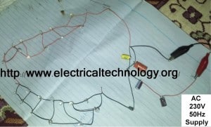
The second one ( Circuit diagram) which i have tried so here is the result.
(click image to enlarge)
in real ( i did not make the circuit on PCB, that’s why i m saying that pleas be careful) supply voltage off.
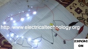
(click image to enlarge)
Supply voltage on and LED’s glow
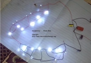
(click image to enlarge)
Another view
(click image to enlarge)
Designed and Prepared by: Wasim Khan
Copyright: https://www.electricaltechnology.org/


Can you please tell me what is the purpose of connecting wire between two LED lines<br />after each LED<br />And what is benefit of making two groups of LED's
FURQAN463@<br />(1).. Making two LED's in Parallel and so on.<br />(2).. Actually it seems that there are two Strings or Two LED's Groups,,,but if you design this circuit on general PCB or in any simulation program. you will find that it is the same (i.e one and only one) String or Group of LED's.
I got the 2nd point<br />1)why to make LED's parallel?<br />No current flows through these wires at any time<br />what if these wires are not inserted
Dear FURQAN463@<br />If you design this whole circuit in a notebook paper without inserting that wires, you will find that their will be 4 strings each having 6 LED's. and these LED's will be in Series.<br />So then try to make the same circuit with that specific wires. it will clear that each of two LED's will be in parallel.
can v increase LEDs more <br />
Dear NAGA YADAV@<br />Nice Question… I have updated all the Description…Please refer to the "Common Question about this Circuit" above. You will get the answer. thanks
Awesome circuit. Pretty simple. I set up this way. however the resistor in the circuit is burning out in less than a minute. Im waiting eagerly for a solution.<br />I connected 24 leds with one resistor and one capacitor in series.<br />1kohm/3w<br />.22uF/1200w
Heya i am for the first time here. I came across this board and I in finding It truly helpful & it helped <br />me out much. I'm hoping to give something again and help others like you <br />aided me.<br /><br />Here is my page … <a href="http://www.mensmusclediet.com/male-enhancement/blastxl-natural-male-enhancement-review" rel="nofollow">blastxl</a>
sir how can i construct a more bright light led circuit operated on 220v ac
Good afternoon friends.<br />My name is john, my passion to design an LED star lighting system is very intense but i don't have the complete knowledge yet, that is why i decided to access the internet to acquire more knowledge, in search i found your blog, with what i saw i was amase and as well happy because i know i can get some aid from you.<br /><br />My question is if my main is 220V,
Dear,<br />Read this article<br />How to calculate the value of resistor for LED’s (with different types of LED’s circuits)<br />https://www.electricaltechnology.org/2013/08/how-to-calculate-value-of-resistor-for-LED-circuits.html
What is purpose of inserting the capacitor in series with circuit ……
what is the benefit of this grouping of led's ?<br />and what is the advantage of this type circuit over a circuit in which we connect all led's in series and a resistor accordingly without capacitor ?<br />also, what is the purpose of capacitor in first diagram, doesn't it cause over-voltage in the circuit whenever the ac cycle gets reversed ?<br /><br />also, isn't it dangerous
the capacitor drops the voltage from 220v to approx. 4.5v AC and the resistor limits the current to make it suitable to run the LEDs
how to design a circuit in which which i want different LED'S to glow for different voltages<br />like given 1V only red led should glow,for 2V only green led should glow,3V only blue led should glow
Hi. I'll be trying this out once I have all the materials (LEDs, cap, and res). My question is what capacitor and resistor should I use if I wanted to use 36 LEDs? Can I use the ones for the 50's? I've checked out the 'how to calculate' link above but it only discussed calculating for the resistor (great refresher – for DC, but we're dealing with AC (the mains) so you
There !!! I have one question which is already in previous comment but there is not any ans. For this..
my que. Is that ” why we use capacitor in circuit???”
Two points I want to raise
1. I agree with FURQAN463, no current flows through the wires and its only a wastage of resources
2. This circuit may flicker at 50 or 60 Hertzs/sec
Am tying to make the 1st circuit, can I use 0.1uf 400v instead of 1000v,
What is the cost of 15w circuit?
Thanks for the simple LED project.
Wohh just what I was looking for, appreciate it for putting up.
I really like your writing style, excellent information, thank you
for posting :D.