How to Wire Twin Timer with Photo Eye Circuit for Time Delay?
Wiring the Twin Timer with Photocell to Delay Switching-OFF Operation of the Light at Dusk
In today’s wiring guide, we will illustrate how to wire a twin timer with a dusk-dawn photocell sensor for post light control. The general circuit is is used to control the light via photoelectric switch, but with the help of twin timer, it delays the switching OFF operation of the photo eye circuit for a predefined time (say 4 hours).
Purpose of the Circuit: The aim of the circuit is to turn the light off four hours after dusk, meaning it should delay the switching-off operation of the circuit at night. This way, the light will remain illuminated for an extended period in the evening.
Related Post:
- How to Reverse Operation of Photo Eye using ST01 Timer?
- How to Wire ST01 Timer for Dusk-Dawn On-Delay Light Control?
Twin Timer:
A twin timer is a versatile electronic device commonly used in industrial automation and control systems. It consists of two independent timer circuits within a single unit, each capable of generating time delays or controlling timing functions separately.
Twin timers are designed to provide precise and adjustable timing control for various applications, such as sequencing processes, controlling relay operations, or managing events in manufacturing and machinery.
Operators can set different time intervals and delay durations for each timer circuit, making twin timers a valuable tool for coordinating multiple actions and ensuring precise timing synchronization in complex systems. These timers are essential components in automation and control systems, contributing to enhanced efficiency and reliability in a wide range of industrial processes.
Photo Eye:
A photo eye, also known as a photoelectric sensor or photocell, is a common type of sensor used in automation and control systems. It operates by emitting a light beam, typically infrared or visible light, and detecting changes in that beam caused by the presence or absence of an object.
When an object interrupts the light beam, the sensor registers this change and generates an electrical signal, which can be used to trigger various actions or responses in automated systems. Photo eyes are widely employed in applications such as object detection, counting, conveyor belt control, and even security systems.
Their versatility and ability to operate in diverse environmental conditions make them an essential component for ensuring accuracy and efficiency in a wide range of industrial and commercial processes.
Related Posts:
- How to Wire Twin Timer for 120V/240V Circuits – ON/OFF Delay
- How to Wire One-Shot Timer using Twin Timer For Delay?
Wiring the Circuit
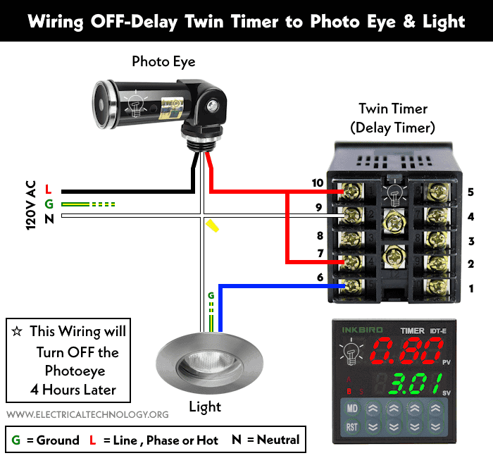
As shown in the wiring diagram for the 120V AC circuit used to control the photo eye via the twin timer, the Line (phase) wire is directly connected to the photocell.
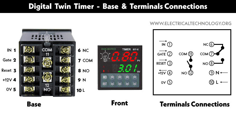
A common wire from the phase terminal (10) and the COM terminal (7) of the twin timer is wired to the photoelectric switch.
The NC (normally closed) terminal (6) of the twin timer is connected to the light.
The neutral wire is connected to all the components, i.e., the photo eye, the light, and the (N) terminal (9) of the timer. Wire the protected ground to each device according to the codes.
Related Posts:
- How to Toggle between Two Heat Pumps using 240V Twin Timer?
- How to Toggle Electric Water Heater Between 120V and 240V?
Working of the Circuit
As the timer’s circuit is wired for OFF-delay operation, it does not turn off the load immediately. Instead, it delays the operation and switches off the load circuit when the preset time expires.
In normal operations, the light turns ON at dusk and switches off at dawn. By adding the delay timer to the circuit with a delay time setting, the light will turn OFF after 4 hours, which is later than the usual dusk time.
The timer can be set up for OFF-delay operations according to the required time interval, such as hours, minutes, or seconds, etc.
When the photo eye sensor activates, it energizes the timer coil, causing the light to turn ON. When the counting ends, i.e., when the time setting in the timer expires, the light turns OFF.
As the timer resets to zero, both the light and the twin timer remain OFF. The cycle repeats again on the next night, providing a delayed operation for the light.
Limitation
- Current Rating: The timer can be used for 5A at 100 to 240V AC.
- Time Range: 0.01 seconds to 99 hours & 99 minutes
- Good to Know: See user manual for exact rating for other brands like SESTOS, Inkbird, Omron DH48S or H3CR, H5CX-A etc.
Related Posts:
- How to Wire ON-Delay Timer for 120V and 240V Load Circuits?
- How to Wire OFF-Delay Timer for 120V and 240V Load Circuits?
- How to Wire AH3 OFF-Delay Timer and Relay with Boiler Fan?
- How to Wire Remote Control Countdown Timer?
- How to Wire Spring Wound Timer with LYS Rely for ON/OFF Delay
- Difference Between ON Delay and OFF Delay Timer
- How to Wire ON/OFF Delay Timer for AC & DC Loads – 230V & 24VDC
- Automatic & Manual Control of 3-Phase Motor Using Delay Timer
- Wiring of DOL Starter for Automatic / Manual Control Using Digital Timer
- Automatic ON/OFF Circuit Using Two 8-PIN Timers for 1 & 3-Φ Load
- How to Wire Multifunction ON/OFF Delay Timer for 120V/240V Motors?
- How to Reduce Runtime of Air-Conditioner During Peak Hours?
- How to Control 120V & 240V Water Heater using ST01 Timer and Contactors?


