Types of Insulators used in Power Transmission and Overhead Lines
Insulators: Types, Properties, Material, Causes of Failure and Applications
The insulators or line insulators are used in overhead transmission and distribution lines. The overhead conductors are supported on the poles or towers. In order to avoid the flow of current through supporting poles, the insulators are used to support the line conductors. Hence, the line insulators are used to provide insulation to the power conductor from the ground.
In a high-voltage transmission line, the conductors are bare and it uses are as an insulator between two conductors. Also, it is not covered with any insulation coating. Generally, the insulators are connected on the cross-arm of the supporting structure to provide necessary clearance between conductors and the metal body. And an insulator clamp is used to pass the conductor. To prevent the flow of any leakage current from line to ground, these insulators provide necessary insulation.
Properties of Insulator
The following properties are desirable in insulators that are used in overhead lines;
- It has high electrical resistance to avoid flowing any leakage current.
- The insulators are able to withstand conductor load and wind. Hence, it should have high mechanical strength.
- It should have high relative permittivity to increase the dielectric strength.
- Puncture to flashover ratio must be high.
- The material used for an insulator is non-porous, free from impurities and cracks. Impurities may reduce permittivity.
- The insulator material must not be affected by a change in temperature.
Insulator Materials
The following different types of insulating materials are used to make a typical insulator.
- Porcelain Insulator: (based on ceramic material i.e. china clay, quarts, aluminum silicate, plastic kaolin, feldspar)
- Glass Insulator: based on toughened glass having high dielectric strength up to 140kV/cm.
- Steatite Insulator: bases on magnesium silicate (different % of magnesium oxide + silica).
- Polymer Insulator: based on fiberglass and epoxy polymer.
Porcelain Insulator
Porcelain is the most commonly used material to make insulators for an overhead transmission line. Porcelain does not allow to pass electric charge and it works efficiently when it is combined with other non-conductive materials. It is aluminum silicate mixed with quartz, feldspar, and plastic kaolin. This results in hard and glazed material that is ideal for an insulator.
Glass Insulator
Annealed glass material is used for insulators and it is useful in transmission and distribution systems. The glass is cheaper than porcelain. The dielectric strength of glass is 140 kV/cm and it is more than porcelain. It has high resistivity and a low coefficient of thermal expansion.
Mostly the glass used as an insulator is transparent. Therefore, the impurities or air bubbles can be easily detected, and also, it is not heated up from sunlight like porcelain. But the disadvantage of a glass insulator is that the moisture can condense the glass surface and provide a path to the leakage current.
Note: If you want to know more, we have a detailed post on the “differences between Glass Insulators & Porcelain Insulators“.
Polymer insulator
There are two types of polymer material used in the system; glass fiber reinforced epoxy resin and silicon rubber. Silicon rubber is also known as EPDC (Ethylene Propylene Diene Monomer) and it is made from weather sheds. Polymer insulators are also known as composite insulators. The polymer insulator is lightweight compared to glass and porcelain insulators. But it has more moisture effects.
Suitable Materials used for Insulators
The suitable material to achieve the above properties are; toughened glass, glazed porcelain, and composite polymer. The toughened glass is obtained by rapidly cooling the glass insulator after shaping and allowing the interior to cool slowly. In this way, the glass insulator has the outer surface in compression and the inner surface is in tension.
Toughened glass can withstand greater tension compared to annealed glass. The cost of toughened glass is less compared to porcelain. In most cases, the toughened glass is transparent. Therefore, the flaws in a material can be detected easily by visual. But the moisture affects the surface of the glass and it causes leakage in the surface of an insulator. Another disadvantage of glass is that the mass of a high-voltage line may irregulate the shape and it may result in internal strain. Due to this, the toughened glass is rarely used in a system and it is only suitable for lines below 25 kV.
The porcelain is made up of clay, quartz or alumina, and feldspar. It is necessary to glaze the porcelain to keep the surface relatively free from dirt and moisture. The dielectric strength of porcelain is about 4-10 kV/mm. The dielectric strength of glass is more than that of porcelain. Any impurities available in porcelain may reduce the dielectric strength of the insulator. Hence, it is essential to confirm the porcelain is air free and impervious to the entry of gases and liquid.
Some utilities have started to use insulators made from polymer composite materials. This type of insulator is composed of fiber-reinforced plastic and the outer surface is silicon rubber or EPDM (Ethylene Propylene Diene Monomer) rubber to avoid weather hazards. The composite insulators are cheap in cost and light in weight. This type of insulator is also suitable in a polluted environment.
Related Posts:
- Corona Effect & Discharge in Transmission Lines & Power System
- Overhead Lines Protection – Faults and Protection Devices
Types of Insulators
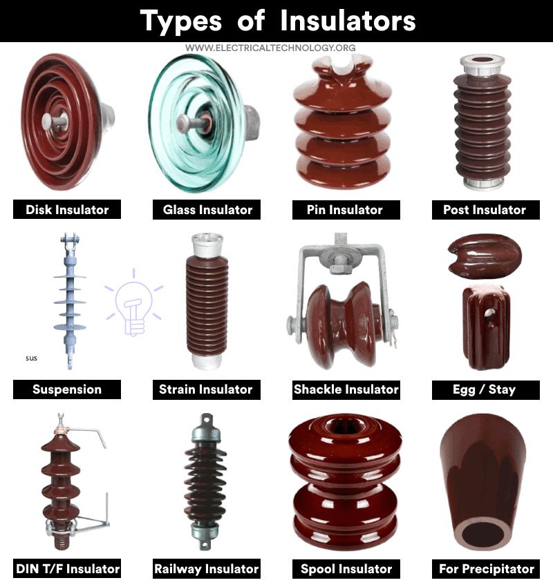
There are various types of insulators are used in the transmission and distribution network which are listed below;
- Pin Type Insulator
- Disk Type Insulator
- Suspension Type Insulator
- Post Insulator
- Strain Insulator
- Shackle Insulator (Spool)
- Stay or Egg Insulator
- Special Types of Insulators
Click image to enlarge
Pin Type Insulator
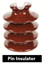
A pin type insulator or pin insulator is small, simple in construction, and cheap in cost. In most cases, this type of insulator is used in the distribution system up to 33 kV lines (they are generally used for 11kV but not more than 50kV). The pin insulator is mounted on a pin on the cross-arm of the supporting structure.
There is a groove on the top of the insulator to place the conductor. A soft metal (generally lead) is used to avoid direct contact between the porcelain and metal pin. One piece of an insulator is used for lower voltages and an adequate length of leakage path is obtained by providing the insulator with two or three rain sheds or petticoats. The rain sheds or petticoats are designed to have sufficient electrical resistance even if the outer surface is wet due to rain.
The thickness of the insulator is required high in case of higher voltage. And it is practically difficult to manufacture pin insulators with high thickness. Hence, two or three insulators are joined and used for higher voltage systems. Generally, pin type insulators are used up to 33 kV system because for higher voltage it becomes heavy and more costly. So, for higher voltage levels, the suspension type insulator is preferred compared pin type insulator for economic reasons.
Disk Type Insulator
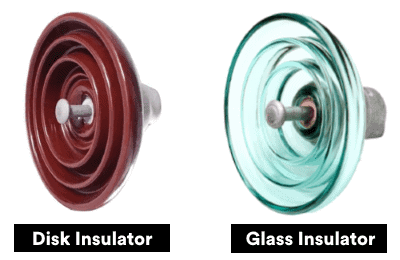
An insulator in the shape of a disk or a plate is known as a disk type insulator. These types of insulators are widely used in low and medium as well as high voltage transmission and distribution due to the required electro-mechanical strength in the polluted environment at comparable low cost.
Disc type insulators are used in high voltage transmission and distribution systems. It is also used in industrial and commercial applications. The disc insulators are cost-effective and can be used in medium and low-polluted environments. The shape of this insulator looks like a disc. Hence, it is known as a disc insulator.
Suspension and strain insulators are two types of disc insulators. It provides good mechanical strength and high resistivity. Dialectic strength is also good in disc insulators. Rubber, plastic, glass, mica, or wood can be used to manufacture the disc insulator. The material used to make a disc insulator depends on the voltage rating of the system and environmental conditions.
There are additional three types of disk insulators based on degree of pollution and creepage distance (The shortest distance of outer surface of insulation material between two conducting parts).
- Normal Type
- Semi-fog Type
- Anti-fog Type
The following table shows the creepage distance and degree of pollution for insulators.
| S. No | Degree of Pollution | Recommended Creepage Distance |
| 1 | Clean areas | 16mm/kV |
| 2 | Moderately Polluted Area | 20mm/kV |
| 3 | Industrial Area | 22mm/kV |
| 4 | Heavily polluted Area | 25mm/kV |
Disk insulator (both glass and porcelain insulators) has more additional types such as suspension type and strain insulators which are furtherly discussed below.
Suspension Type Insulator
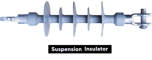
The suspension type insulator is also known as the disc type insulator. The cost of the pin type of insulator increases rapidly with an increase in line voltage. Hence, the suspension type insulator is used over 33 kV line voltage.
This type of insulator uses porcelain discs. The porcelain discs are mounted one above the other and make a string. To increase the creepage distance, each disc consists of a single shed of porcelain grooved under surface. The upper surface of a disc is inclined at an angle to ensure free draining of water. Each disc has a metal cap and a metal pin. The metal cap is provided on the top and the metal pin is provided underneath. So, the cap is fitted with the pin of another unit and it helps to connect a number of discs together.
The conductor is suspended below the point of support with insulation string. Hence, this type of insulator is known as a suspension type insulator. The string of an insulator is flexible and it provides adequate clearance between conductors and between conductor and metal body when the string swings in wind.
There are three types of suspension type of insulators as follows:
- Hewlett Type Insulator: It is the old school design and contains only one porcelain disk.
- Cemented Cap Type Insulator: It is also contained on one porcelain disk and there is a slot in the bottom (to improve the flashover ability) where a conductor can be connected to it. There is a galvanized cast iron cemented cap on the upper portion of the insulator, that’s why it is known as a cemented cap type insulator.
- Core & Link Type Insulator: It is the combination of above mentioned two types of insulators e.g. Hewlett + cemented Cap.
The suspension type insulator has many advantages compared to the pin type insulator. Some of these advantages are;
- The insulation string is flexible. Hence, it reduces mechanical stress.
- Each disc is designed for low voltage. But a number of discs are connected together to make a string according to a required voltage level. If one disc is failed, only that disc is needed to replace instead of an entire string.
- If it is proposed to increase the line voltage, the line insulation is increased by the increased number of discs.
The number of discs in a string depends on the line voltage and the atmospheric conditions. But, in most cases, a number of discs for different volage ratings are shown in the table below.
| Voltage kV | 33 | 66 | 110 | 132 | 220 | 440 | 500 |
| Number of Discs (Suspension) | 3-4 | 5-6 | 7-8 | 9-10 | 13-16 | 22-23 | 25-26 |
Voltage Distribution Over Suspension Insulator String
In a suspension insulator, the number of discs is connected in series with a metal cap and pin. Therefore, each disc acts as a capacitor C. Also, there is a mutual capacitance between the metal connector to earth and it is represented by kC. The illustration of four suspension insulators is shown in the figure below.
Fig-3
Consider that V1 is the voltage difference between two metal conductors of the first insulator.
Now,
I1 = V1 ω C
i1 = V1 ω kC
According to KCL;
I2 = I1 + i1
I2 = V1 ω C + V1 ω kC
I2 = V1 ω C (1 + k)
Also, for the second insulator;
I2 = V2 ω C
Hence,
V1 ω C (1 + k) = V2 ω C
V2 = V1 (1 + k)
i2 = k ω C (V1 + V2)
i2 = k (2 + k) V1 ω C
For the third insulator;
I3 = I2 + i2
I3 = k (1 + 3k + k2) V1 ω C
I3 = V3 ω C
V3 = k (1 + 3k + k2) V1
i3 = k ω C (V1 + V2 + V3) = k (3 + 4k + + k2) V1 ω C
For the fourth insulator;
I4 = I3 + i3
I4 = k (1 + 6k + 5k2 + k3) V1 ω C
I4 = V4 ω C
V4 = k (1 + 6k + 5k2 + k3) V1
The value of ‘k’ lies between 0.1 to 0.2.
String Efficiency:
String efficiency of ‘n’ units is defined as;
The string efficiency decreases with an increase in the number of disc units.
Related Posts:
- Electrical Transmission Networks – EHV and HV Overhead Lines
- Busbars and Connectors in HV and EHV installations
Post Insulator
A post insulator is similar to a pin type insulator. But post insulator has a metal base and metal cap that helps to mount more than one insulator in series. This type of insulator is used in supporting bus bars and disconnecting switches in the sub-station.
The post insulator is used in extra high-voltage sub-stations. Polycon post insulators are used in 400 kV and above systems. This insulator is a puncher-proof, solid core insulator suitable for outdoor applications.
This insulator is mostly used in substations and similar applications. Hence, this insulator is also known as a station post insulator. And in transmission line applications, this insulator is known as a line insulator. There are five types of line post insulators;
- Vertical clamp top line posts
- Tie top-line posts
- Horizontal (stud mount) clamp top line posts
- Brace post insulators
- Horizontal (gain base) line posts
Strain Insulator
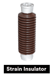
The strain insulators are specially designed to have high mechanical strength. And these insulators are able to withstand the tension of the conductor at the line ends. The strain insulators are used to support overhead transmissions and radio antennas. It is also used to separate two wires electrically.
The strain insulator is made up of glass, porcelain, or fiberglass. For a lower voltage system, a single insulator is used. But for a higher rating, the number of insulators are connected in series. This type of insulator is used in long transmission lines. And also, it is suitable to provide mechanical strength when the line crosses the lake, river, or pond.
The following table shows the required number of strain string (discs) and related voltage levels.
| Voltage kV | 33 | 66 | 110 | 132 | 220 | 440 | 500 |
| Number of Discs (Strain String) | 4-5 | 6-7 | 8-9 | 10-11 | 14-17 | 23-24 | 26-27 |
Related Posts:
- All About Electrical Protection Systems, Devices And Units
- Failures In Electrical Systems, Equipment & Materials
Shackle Insulator
A shackle insulator is used in a low-voltage distribution network. This type of insulator can be used either in vertical or horizontal positions. The shackle insulator is also known as a spool insulator. In a recent power system (transmission and distribution) scenario, the distribution networks use an underground system. Hence, usage of shackle insulators is decreased.
The shackle insulator is available in different sizes and round shapes. It has a hole in the middle for boulting. A wide galvanized plate is placed on both sides. The surface of an insulator is covered to resist water flow. It is manufactured from porcelain and aluminum silicate. The conductors are fixed within the groove using a soft binding wire. The shackle insulators are designed to provide insulation between the tower and conductor in the distribution system.
Stay or Egg Type Insulator
Egg or stay insulators are used to insulate the stay or guy wire from the low voltage lines. Stays are installed minimum 13 meters above the ground level and insulated from the ground via porcelain insulators. The special design of the stay insulator won’t allow the guy wire on the ground even if it breaks.
In stay paths, this type of insulator is used. In case of wire cuts or falls on the ground, the stay insulators help to avoid current flow from conductor to ground. Therefore, this type of insulator is placed between the tower and the line conductor. This insulator is mainly used on guy wire to balance tensile.
Generally, the stay insulators have been installed in the middle of the stay path. And in most cases, it is made up of porcelain material. The stay insulators are used for low voltage overhead transmission systems.
There are two vertical slots in the stay insulator which are used to fix the guy wire and line wire in each of them. Generally, these insulators are used in stays, that’s why it is known as stay insulators.
Related Posts:
- HV And MV Switch Disconnectors And Isolators in Power System
- MV & HV Cable Termination to Equipment & Joints
Special Types of Insulators
Areas where the air conditions are not favorable or normal, for example where there is smoke, chemicals, salts or humidity in the environment etc. then special types of insulators are used instead of normal insulators e.g.:
- Pin Type Anti-dirt insulators: It has more creepage distance (490mm) than the normal insulator which is generally 325 mm. The rain water can easily go inside the shades of these insulators which helps to clean the dirt.
- Inclined Disk Insulators: Looks like disk type suspension insulator but not in complete horizontal plane but bend-over at a specific angle.
- Deep Shade Insulators: It has deep and large shades as compared to prevent the puncturing problems of Inclined Disk Insulators in the rainy seasons.
- Solid Core Insulators: It has a solid core without a slot which is used to fit the pin inside it. The pin is connected to the lower portion of the insulator using cement.
- Aerodynamic Insulators: It has small shades as compared to the deep shade insulators hence, it prevents the dirt and resist even in the strong wind. They are used in sandy areas and desert landscapes.
Except all of the above mentioned types, there are some additional types of insulators used in substations as follows:.
Substation Insulators:
- Post Insulators for Support
- Sectionalizing Insulators
- Bracket Insulators
- Tensile Load Insulators for Driving / Pulling Live parts
- Operating Rod Insulators
- Stray Arm Insulators
- Shaft Insulators
- Roofline Insulators
- Connecting Rod Insulators
Related Posts:
- Why is Electric Power Transmission Multiple of 11 i.e 11kV, 22kV, 66kV etc?
- What are the Colored Aerial Marker Balls on Power Lines For?
Selection of Insulators
The first thing before proper selection of the insulator is to know the exact value of the insulation level of the lines in terms of the terminal equipment. In addition, the normal frequency flashover voltage and lighting voltages are considered while selecting an insulator.
Another factor is the effect of the line insulation efficiency on supporting structures (wood, steel etc.) this way, the construction, design and usable age of the cross arms and poles & towers should be considered for choosing the suitable insulators.
The overvoltage due to switching surges and arcing ground because of isolated neutral systems can affect the over insulation, In addition, the proper information about the mechanical stress should be taken into account while selecting an appropriate insulator for the designed system.
As a final touch, the manufacturers catalogs based credible data helps a lot to select the suitable insulator for reliable operation of the systems.
Related Posts:
- What is the Purpose of Ground Wire in Overhead Transmission Lines?
- Why Power Transmission Lines are Loose on Electric Poles & Transmission Towers?
Causes of Failure in Insulators
There are some common causes of failure in the insulator listed below.
Cracking of Insulator:
Due to unequal expansion, there is a chance of a crack in the porcelain insulator. Also, by the seasonal effect, there is a chance to crack in an insulator. There are many improvements needed to avoid such cracking. Sometimes, the cushions are used between shells and steel pins to allow some expansion.
Defective material:
Generally, the insulator is manufactured from good materials. But there is a chance of defective material. And it causes puncture that allows to flow of the current. These defective insulators are not used in electrical systems.
Porosity of material:
Generally, the insulators are manufactured from porcelain. If the porcelain is manufactured at a lower temperature, it will make it porose. Hence, it will absorb moisture from the air and it may allow flowing leakage current. Therefore, this is unfit to use in electrical networks.
Improper glazing on the surface:
The outer surface of the insulator is glazed properly to free the draining of water. But, if the glazing is not properly done, there is a chance to stick moisture on it and depositing dust on the surface of an insulator. It causes a conducting path and it results in a reduction in a flash over distance. Hence, there is more chance of flashover in an insulator.
Flashover
If the flashover occurs between the two metallic ends of the insulator and generates high temperature and heat which leads to breaking the insulator.
Short circuit
If the distance between the conductors is short, there is a chance of arcing due to the bird strikes on line conductors. This cause of short circuit may also lead to failure of the insulator.
Mechanical stress:
The mechanical stress on the insulator is continuously applied by the conductor. If the insulator is manufactured from defective material, it may break down from a weak point and causes the failure of an insulator.
Related Posts:
- Design and Installation of EHV/EHV and EHV/HV Substations
- Classification of Electric Power Distribution Network Systems
- Types of HVDC Systems and MTDC Configurations
- Advantages of HVDC over HVAC Power Transmission
- Differences Between HVAC and HVDC – Power Transmission
- Differences Between HVAC and HVDC – Power Transmission
- Difference between AC and DC Transmission System & Power Lines
- Difference between Lightning Arrester and Surge Arrester
- What is Shunt Reactor – Types, Construction & Applications
- Power System Restoration – Outage, Voltage Collapse & Switching Programs
- Electrical Shock Hazards & Its Effects on Human Body
- Types & Characteristics of Surge Arresters
- Electric Stress Control in Cable, Joints & Terminations
