Superposition Theorem – Circuit Analysis with Solved Example
Superposition Theorem – Step by Step Guide with Solved Example
What is Superposition Theorem?
The Superposition Theorem is used to solve complex networks with a number of energy sources. It is an important concept to determine voltage and current across the elements by calculating the effect of each source individually. And combine the effect of all sources to get the actual voltage and current of the circuit element.
Superposition theorem states that;
“In any linear bilateral network having a greater number of sources, the response (voltage and current) in any element is equal to the summation of all responses caused by individual source acting alone. While other sources are eliminated from the circuit.”
In other words, we will consider only one independent source acting at a time. So, we need to remove other sources. The voltage sources are short-circuited and the current sources are open-circuited for ideal sources. If the internal resistance of sources is given, you need to consider the circuit.
The superposition theorem is only applied to the circuit which follows Ohm’s law.
When to Use the Superposition Theorem?
The network must follow the below requirements to apply the superposition theorem.
- The components used in the circuit must be linear. It means, for resistors, the flow of current is proportional to the voltage; for inductors, the flux linkage is proportional to current. Therefore, the resistor, inductor, and capacitor are linear elements. But the diode, transistor is not a linear element.
- The circuit components must be bilateral elements. It means, the magnitude of the current is independent of the polarity of energy sources.
- With the help of the superposition theorem, we can find the current passes through an element, voltage-drop of resistance, and node voltage. But we cannot find the power dissipated from the element.
- Related Post: Norton’s Theorem. Step by Step Guide with Solved Example
Steps to Follow for Superposition Theorem
Step-1 Find out a number of independent sources available in the network.
Step-2 Choose any one source and eliminate all other sources. If the network consists of any dependent source, you cannot eliminate it. It remains as it is throughout the calculation.
If you have considered all energy sources are ideal sources, you need not consider internal resistance. And directly short-circuit voltage source and open-circuit current source. But in case, if internal resistance of sources is given, you have to replace internal resistance.
Step-3 Now, in a circuit, only one independent energy source is present. You need to find a response with only one energy source in the circuit.
Step-4 Repeat step-2 and 3 for all energy sources available in the network. If there are three independent sources, you need to repeat these steps three times. And every time you get some value of the response.
Step-5 Now, combine all responses by algebraic summation obtained by individual sources. And you will get a final value of response for a particular element of a network. If you need to find a response for other elements, you need to follows these steps again for that element.
Superposition Theorem Solved Example
Example:
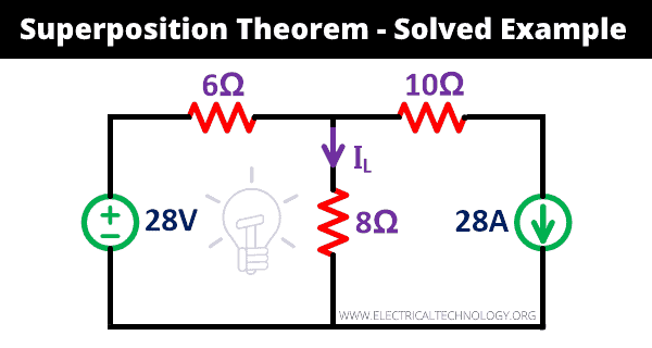
Let’s understand the working of the superposition theorem by example. Find the current (IL) passes through the 8Ω resister in the given network using the superposition theorem.
Solution:
Step-1 As shown in the above network, one voltage source, and one current source is given. Therefore, we need to repeat the procedure two times.
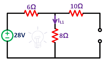
Step-2 First we consider 28V voltage source is present in the network. So, you need to remove the current source by open-circuited terminals. As here, we consider the current source as an ideal current source. So, we need not connect the internal resistance.
The remaining circuit is as shown in the below figure.
Step-3 Find the current (IL1) passes through 8Ω resister. It gives the effect only of a voltage source.
Due to the open circuit of a current source, no current passes through the 10Ω resister. So, the network consists of only one loop.
Apply KVL to the loop;
28 = 6IL1 + 8IL1
28 = 14IL1
IL1 = 28/14
IL1 = 2A
Step-4 Now, we repeat the same procedure for the current source. In this condition, we remove the voltage source by short-circuiting. A remaining circuit is as shown in the below figure.
Here, we have to consider two loops. I1 and I2 are loop current. And find the current IL2.
Apply KVL to the loop-1;
0 = 6I1 + 8I1 – 8I2
14I1 – 8I2 = 0
The current passes through the loop-2 is calculated from the current source. And it will be;
I2 = 28A
Put this value in the above equation;
14I1 – 8 (28) = 0
I1 = 16A
Now, the 8Ω resister branch is common in both loops. So, we need to find the resultant current (IL2) passes through the 8Ω resister.
IL2 = I1 – I2
IL2 = 16 – 28
IL2 = -12A
Step-5 Now, we combine the effect of both sources by algebraic summation of current. So, the total current passes through the 8Ω resister are IL. Here, the direction of the current is most important. Current IL2 has a minus sign. It means during the 28A source, the current flows in opposite direction. And we cannot change the direction. That’s the reason while combining all sources, we are doing algebraic summation.
IL = IL1 – IL2
IL = 2 + (-12)
IL = -10A
Here, we have assumed that the current passes through the 8Ω resister are in the direction of the arrow shown in the figure. Minus sign shows the opposite direction. And the amount of current is 8A.
Superposition Theorem Experiment
The superposition theorem experiment can be done by following the below steps.
Aim
Determine the current flowing through the resistors and verify the superposition theorem.
Components Required
DC source, Resistors, DC multimeters, Connecting Wires, Breadboard, etc.
Theory
Superposition theorem is used in circuit analysis to find the current and voltage across the elements in a given circuit. This theorem is useful when the number of sources is more.
According to the superposition theorem, the response of elements is an algebraic summation of response from the individual energy sources.
First, we will calculate the current passes through resistors in a given network. When all sources are connected. After that, we remove sources and find currents for individual sources. At last, the summation of current measured from the individual sources is similar to the current measures with all sources connected.
Procedure
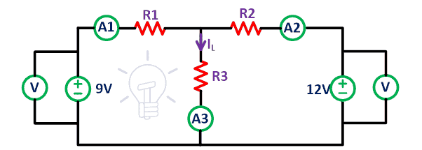
We consider the linear bilateral circuit given in the below figure.
Connect all elements on the breadboard as given in the above circuit using connecting wires. Connect ammeter with all resisters to find the current passes through the resistors. Here, we have two voltage sources.
In the first case, measure the current that passes through all resisters when both voltage sources are present in the circuit. The current flowing through the resistor R1, R2, and R3 is I1, I2, and I3 respectively.
Now remove the 12V voltage source from the circuit. Short the terminals A’ and B’ as shown in the above figure. Here we have assumed that the voltage sources are ideal. So, no need to connect internal resistance. Now, measure the current I1′, I2′ and I3′ which is the current that passes through the resistor R1, R2, and R3 respectively.
Similarly, remove the 9V voltage source and the remaining circuit is as shown in the above figure. Again, measure the current flowing through all resisters and name it I1“, I2“, and I3“.
- Related Post: Maximum Power Transfer Theorem for AC & DC Circuits
Put all values in below observation table.
Observation Table
| Source Connection | R1 | R2 | R3 |
| Both sources are connected | I1 | I2 | I3 |
| Only 12V is connected | I1′ | I2′ | I3′ |
| Only 9V is connected | I1″ | I2″ | I3″ |
Calculation:
I1 = I1′ + I1″
I2 = I2′ + I2″
I3 = I3′ + I3″
To verify the superposition theorem, we compare the algebraic summation of current passes through resisters when an individual source is connected with the current measured when both sources are connected in a circuit.
If the above calculation satisfies, we can prove the superposition theorem.
Conclusion
In this experiment, we can prove that the current that passes through the resistance is an algebraic summation of current when an individual energy source is connected. And it proves the superposition theorem.
Application of Superposition theorem
- Superposition theorem can be used for AC and DC networks.
- When the number of independent sources is more, it is easy to find a response of the network.
- It helps to calculate current passes and the voltage across the element by calculating the effect of each energy source individually. And after we can determine the combined effect on elements from all sources.
Drawback of Superposition Theorem
- Superposition theorem cannot apply to the circuit having only a dependent source. It needed at least two independent sources.
- This theorem only applicable to the network which consists of linear elements. It cannot apply to the non-linear elements like a diode, transistor, etc.
- We cannot calculate power by this theorem. As the power is proportional to the square of voltage and current as it becomes non-linear.
- This theorem is not applicable in a condition where the resistance varies with voltage and current. For all energy sources, the value of resistance must remain constant.
- This theorem only applicable to the bilateral elements. If the response of the network depends on the direction of the current, this theorem is not applicable.
Related Electric Circuit Analysis Tutorials:
- Tellegen’s Theorem – Solved Examples & MATLAB Simulation
- Cramer’s Rule Calculator – 2 and 3 Equations System for Electric Circuits
- Wheatstone Bridge – Circuit, Working, Derivation and Applications
- Electrical and Electronics Engineering Calculators
- 5000+ Electrical and Electronic Engineering Formulas & Equations


This was informative, just a little note that you made a mistake with the first example where you have IL2 = 16-28 = -10; it should be -12. I haven’t looked at the other question as yet but the process is correct, just that minor detail i recommend correcting.
The typo has been corrected. Thanks for correction.