How to Run a Three-Phase Induction Motor on a Single-Phase Power Supply?
Running a 3-Φ Induction Motor on a 1-Phase Supply – 3 Methods
According to the type of AC power supply, induction motors are classified into two types; three-phase induction motor and single-phase induction motor. In most industrial and agriculture applications, a three-phase induction motor is widely used compared to a single-phase induction motor.
Due to power deficiency, three-phase power is not continuously available in agriculture applications. In this case, one phase is disconnected from the gang operating switch (GOS). So, most of the time, two out of three phases are available. But with any special arrangement, it is not possible to operate a three-phase motor on a single-phase power supply.
As we know, the three-phase induction motor is a self-start motor. As the stator winding of the three-phase induction motor generates a rotating magnetic field. This will create a 120˚ phase shift. But, in the case of a single-phase induction motor, a pulsating magnetic field is induced. Hence, a single-phase induction motor is not a self-starting motor. It requires some extra auxiliary for starting purposes.
Same here, we need some extra arrangement to do, to operate a three-phase induction motor on a single-phase supply. There are three methods;
- Using Static Capacitor (phase-shifting method)
- Using VFD (variable frequency drive)
- Using Rotary Converter
In this article, we will discuss each method in brief.
Using Static Capacitor
When we supply three-phase AC power to the stator of the three-phase induction motor, a balanced time-varying 120˚ apart rotating magnetic field is produced. But in the case of a single-phase induction motor, a pulsating magnetic field is induced. And in this case, initial torque (starting torque) is not produced. In a single-phase induction motor, an extra winding is used to create a phase shift. Instead of a starting winding, a capacitor or inductor is also used to create phase displacement.
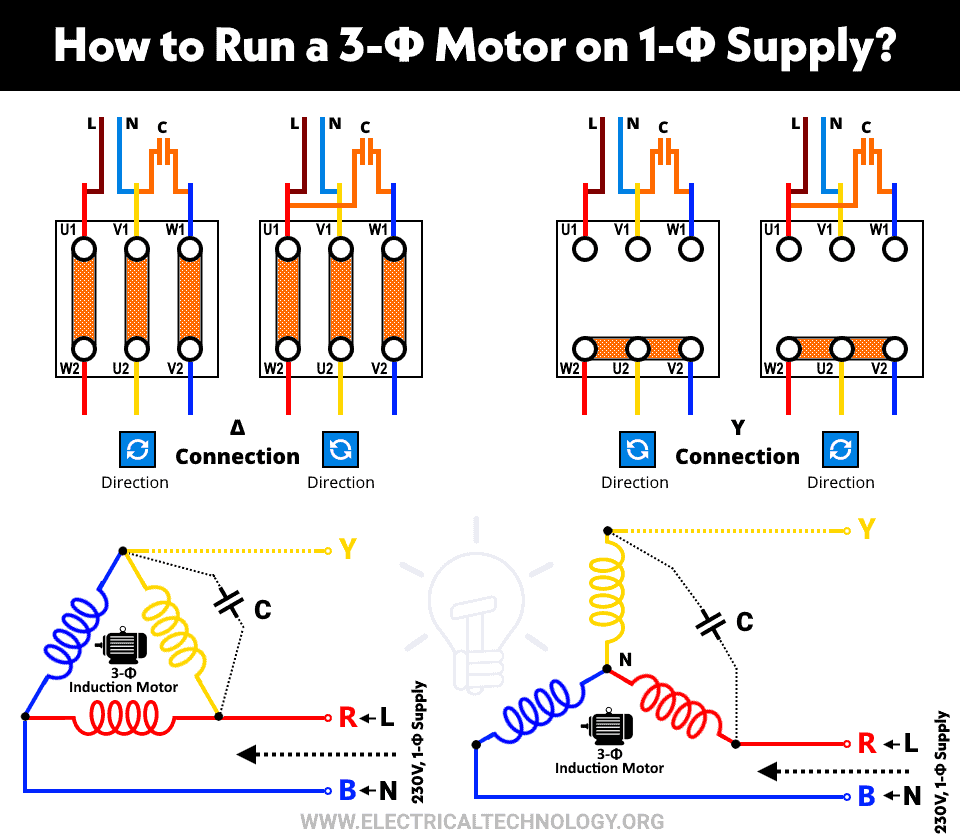
Similar to this principle, we can use three-phase winding of a three-phase induction motor and shift one winding using a capacitor or inductor. Once the three-phase induction motor started on a single-phase supply, it continuously runs on reduced capacity. The net output or efficiency of the motor is reduced 2/3rd of its rated capacity.
This method is also known as the static phase converter method or phase-shifting method or rewinding method.
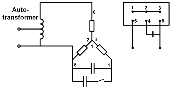
In some arrangements, two capacitors are used; one for starting and the second for running. The start capacitor is 4 to 5 times higher capacity compared to a running capacitor. The circuit diagram of this arrangement is shown in the figure below.
Start capacitor is only used for starting purposes. It will disconnect from the circuit after starting. The running capacitor always stays in the circuit. Here, as shown in the figure, the motor is connected in star connection. And both capacitors are connected in between two phases of winding.
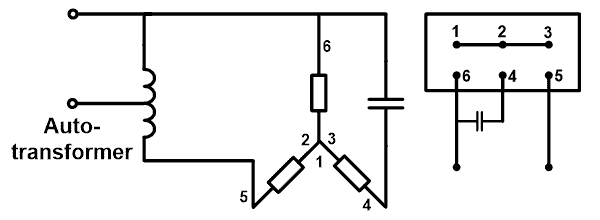
Single-phase supply has two terminals. One terminal is connected to the series combination of winding and the second terminal is connected with a remaining terminal of three-phase winding. Sometimes only one capacitor is used. This type of arrangement is shown in the figure below.
In most cases, small induction motors are connected in star connection. Here, we have taken a star-connected three-phase induction motor. An autotransformer is used to increase the voltage level. Because the voltage level of the three-phase supply is 400-440 V and the voltage level of the single-phase supply is 200-230 V for 50 Hz of supply.
We can use this circuit without using an autotransformer. In that case, the voltage level remains at single-phase power (200-230 V). In this condition also, the motor will run. But as the voltage is low, the torque produced by the motor is low. This problem can be solved by connecting an extra starting capacitor (fig-1). This capacitor is known as starting capacitor or phase-lock capacitor.
If you need to reverse the direction of the motor, change the connection diagram as shown in the figure below.
Limitations:
The limitations of the static capacitor method are listed below.
- The output power of the three-phase induction motor is reduced by 2/3rd of full load power.
- This method can be used for a temporary purpose. It is not suitable for continuous running applications.
- In this method, the loading effect is continuously in two phases. This will reduce the life span of the motor.
Related Posts:
- What happens to the 3-Phase Motor When 1 Out of 3 Phases is Lost?
- What happens to the 3-Phase Motor When 2 Out of 3 Phases are Lost?
Using VFD
VFD means variable frequency drive. It is a device that is used to control the motor (adjustable speed on running). VFD adjusts the input current of a motor according to demand (load). This device allows the motor to operate efficiently over varying load conditions.
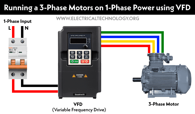
This method is best to operate a three-phase induction motor on a single-phase supply. In this case, an available single-phase supply is given as input to the VFD. VFD converts single-phase supply into DC by rectifying. Again, it converts DC supply into a three-phase AC supply. And the frequency of the three-phase output is adjusted by VFD.
Hence, available power (single-phase) is given to VFD, and output (three-phase power) of VFD is used as input of a three-phase motor. It also eliminates rush current during starting of motor. It also provides a smooth starting of a motor from standstill to full speed condition. There are different types and ratings of VFD available for different applications and motors. You only need to choose the proper VFD for your applications.
The cost of VFD is more than a static capacitor. But it gives better performance of the motor. The cost of VFD is less than the rotary phase converter. So, in most of the applications, VFD is used instead of rotary phase converters.
- For a latest detailed post on it, you may refer to: How to Run a Three-Phase Motor on Single-Phase Supply Using VFD?
Advantages of VFD:
The advantages of using VFD for running a three-phase induction motor on a single-phase power supply.
- By adjusting VFD’s parameter, we can achieve a soft start of the motor.
- It is easy to operate on the best performance with greater efficiency.
- It has a self-diagnosis function that is used to protect the motor from overvoltage, overload, overheating, etc.
- It is programmed to achieve automatic control of the motor.
Using Rotary Phase Converter
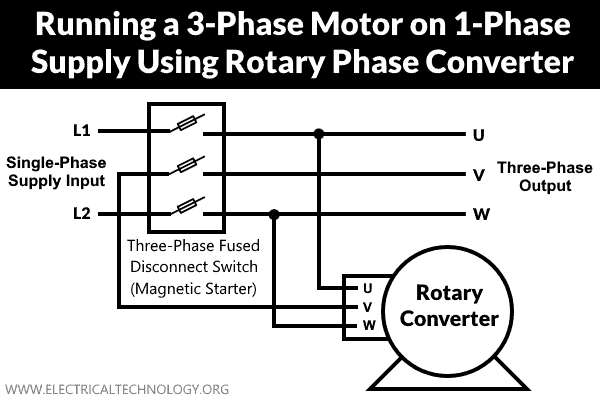
Another method used is to run a three-phase induction motor on a single-phase power supply using a rotary phase converter (RPC). This process is very expensive. It will give the best performance compared to all other methods. Because the rotary phase converter generates a perfect three-phase signal at the output. Then also, it is not used widely as the cost of the rotary converter is very high.
The connection diagram of the rotary phase converter is shown in the figure below.
Related Posts:
- Difference Between Single Phase & Three Phase Induction Motor
- Difference Between Single Phase and Three Phase Power Supply
- Why 3-Phase Power? Why Not 6, 12 or More for Power Transmission?
- If a 1-Phase Supply is 230V, Why is 3-Phase 400V & Not 690V?
- Advantages of Three Phase System Over Single Phase System
- Three Phase Current Values in a 3-Phase System
- Star Connection (Y): Three Phase Power, Voltage & Current Values
- Delta Connection (Δ): 3 Phase Power, Voltage & Current Values



3 phase motor 5 hp star and 5< delta canection Running