LVDT: Linear Variable Differential Transformer – Inductive Sensors
Linear Variable Differential Transformer (LVDT) – Inductive Sensors
Inductive sensors are the type of sensor used to calculate position or speed. Mostly all inductive sensors work based on transformer principle and alternating electrical currents. These sensors makes use of current that gets induced by the magnetic field, which helps them to detect nearby metal objects. An inductive sensor consists of a coil which is usually an inductor. The coil helps to generate magnetic field of high frequency. When a metal object is brought near the magnetic field, there will be a current flow in the object. The generated current creates a new magnetic field which opposes the original field. Finally the net effect is the change of inductance in the inductive sensor. The concept of magnetic coupling between different coils is the basis for all types’ inductive sensors.
Linear Variable Differential Transformer (LVDT):
Introduction to LVDT:
LVDT is a type of electromechanical transducer that helps to convert rectilinear motion of the object into an electrical signal. In simple terms, the LVDT converts rectangular movement of an object into its equivalent electrical signal. Hence LVDT is used to calculate displacement. LVDT is AC controlled, so there is no electronics component inside it and they work at very low temperature. When it converts mechanical motion into electrical signal, it gives the phase and amplitude information of the device also. The entire operation of LVDT works on electromagnetic coupling otherwise called as Mutual Induction concepts.
Construction of LVDT:
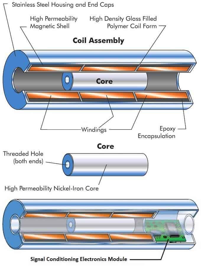
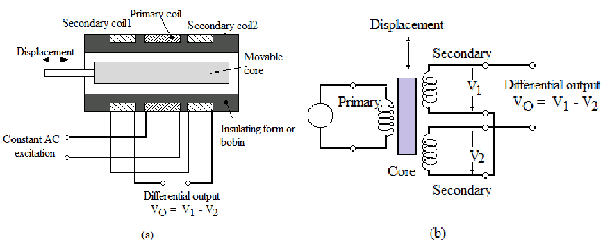
LVDT has basically few main components namely transformer, core and coil assembly. The transformer (core) consists of three wire wound coils fixed in a hollow space. Two primary and one secondary coil are present. Primary coil will be attached between two secondary coils. They are symmetrical and winded in series connections but in opposite direction. The core is made of a material that’s magnetically permeable and it can move freely inside the transformer. The range of AC excitation voltage applied is 5 to 12 V with an operating frequency of 50 to 400 Hz

Working of LVDT:
LVDT works on the principle of mutual induction. The entire working is divided into three cases depending upon the position of iron core.

P is the primary winding that is energized with AC source. S1 and S2 are the secondary windings
Case 1: When the core moves towards S1, the secondary coil on that end becomes strongly coupled to the core. So, E1 is the induced voltage of that secondary coil S1 is higher than the induced voltage E2 of another secondary coil S2. Hence the differential voltage would be E1 – E2, which will describe the amount of displacement of the core. In this case, E1 of the secondary coil is in phase with primary voltage, so this indicates the direction of the movement.
- Related Post: Capacitive Sensor and Tranducer and Its Applications
Case 2: when core is moved to another side of the transformer, the induced voltage E2 of the secondary coil will be out of phase with primary voltage. Since it is out of phase, the movement of the core will be in opposite direction.
Case 3: When the core is in the null position, midway between S1 and S2, equal flux will be developed to both of the secondary winding. Hence, voltages E1 and E2 induced on S1 and S2 will also be equal to each other. So, there will be no displacement.

The below shown is the characteristics graph of LVDT. LVDT has a direct and linear function for specific range of measurement with respect to the input. The graph shows the non-linearity function of LVDT after sometime when core exceeds the range of operation. Polynomial function can be used to rectify the nonlinearity function.
Though we tell LVDT does not have electronics inside it, there can be external electronics called as signal conditioner. This includes oscillator used to generate signal, a demodulator, amplifier and low pass filter which helps to convert AC output voltage into DC signal. In few designs, signal conditioning units are inside LVDT called as DC LVDT.
LVDT Specifications:
- Linearity:
- (0.025 to 0.20 + % or 0.025 to 0.20 – %) Full Scale
- (0.20 to 0.50 + % or 0.20 to 0.50 – %) Full Scale
- (0.50 to 0.90 + % or 0.50 to 0.90 – %) Full Scale
- (0.90 to + % or 0.90 to – %) Full Scale and up
- 90 to ± % Full Scale & Up
- Operating Temperature:
> -32ºF, (-32-32ºF), (32 -175ºF), (175-257ºF), 257ºF & up
- Range of Measurement:
± 0.25 mm to ± 750 mm.
- Related Post: Rain Alarm Sensor– Snow, Water and Rain Detector Project
LVDT Advantages and Disadvantages:
- LVDT has a very high output and it does not need any extension.
- LVDT shows a very less and small hysteresis
- Power consumed by LVDT is very low upto 1W
- It does not have any frictional losses
- The range of measurement in LVDT ranges from 1.25mm to 250mm
- Temperature variation and vibrations affects the performance of LVDT
Related Posts:
LVDT Applications:
- LVDT is used to measure weight, force, pressure and displacement
- LVDT can act as primary and secondary transducer. For example in pressure measurement when Bourdon tube acts as primary transducers, it helps to convert pressure into linear displacement. After which LVDT converts the displacement into an electrical signal. After calibration of the display, the electrical signal gives the reading of fluid pressure.
- These are also used in industrial automation, aircraft & satellites, hydraulic, turbine,
Related Post: Types of Resistive Sensors – Transducer, Potentiometer & Strain Gauge


