How to Control 120V & 240V Water Heater using ST01 Timer and Contactors?
How to Wire ST01 Timer with Relay & Contactor for 120V/240V Water Heater?
In today’s wiring tutorial, we will demonstrate how to wire and control a 120V and 240V water heater with automatic ON and OFF operation using an ST01 timer (or any other digitally programmable timer) and a contactor.
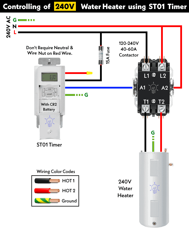
Before proceeding with the wiring installation, it’s important to note that the ST01 timer does not require a Neutral wire. Only the blue and black wires from the timer are connected to the circuit; therefore, the red wire is capped off (secured with a wire nut).
To reverse the dusk-dawn operation using an Intermatic timer (Ei600 or ST01, etc.), simply add a jumper wire from red to blue and connect it to the load. This will reverse the circuit operation from DUSK-DAWN to DAWN-DUSK.
The ST01 timer is rated for 15A. If you intend to use it for high-amperage load circuits, such as a 240V water heater and motors, a relay or contactor is recommended.
The following wiring diagram can be utilized for any other 30A, 120V to 240V load circuits, such as water pump motors, etc.
Related Posts:
- How to Toggle Electric Water Heater Between 120V and 240V?
- How to Toggle between Two Heat Pumps using 240V Twin Timer?
Wiring Timer with 120V Water Heater Using Contactor
As depicted in the wiring diagram, the hot wire (line) from the 120V source is directly connected to the black wire on the timer and the L1 terminal of the contactor. The neutral wire is connected to terminals L2 and A2 of the 40-60 amp contactor.
Click image to enlarge
The blue wire from the timer is directly connected to the coil terminal (A1) of the contactor. As the ground wire is not shown in the wiring diagram, simply connect a bare or green wire to all applicable appliances in accordance with local area codes.
When you complete wiring the circuit as shown in fig, set up the time on the timer according to the requirement to control the circuit operation, and it will automatically turn ON and OFF based on the configured time.
Related Posts:
- How to Reduce Runtime of Air-Conditioner During Peak Hours?
- How to Wire ST01 Timer with Relay & Contactor for 120V/240V Motors?
Wiring Timer with 120V Water Heater using Contactor
Wiring for the 240V water heater follows the same principles as the 120V circuit explained above, with variations in wiring color codes for a clearer explanation. For instance, we used (you may choose to do so as well) a black wire for Line 1 (Hot 1) and red for Line 2 (Hot 2) in the 240V water heater circuit.
Click image to enlarge
Conversely, for the 120V circuit, we used black as Line (Hot) and white as the Neutral wire. A bare, green, or green wire with a yellow stripe should be employed for proper grounding.
Given that the amperage rating of the 240V water heater exceeds the 15A capacity of the digital programmable timer, we incorporated a 40-60A contactor to manage the water heater’s control via the ST01 timer.
Additionally, we installed a 10-15 amp fuse to safeguard the timer circuit from the heavy amperes flowing in the contactor circuit.
Related Posts:
- How to Control Water Heater using Switches?
- How to Wire 3-Phase Non-Simultaneous Water Heater Thermostat?
- How to Wire 3-Phase Simultaneous Water Heater Thermostat?
- How to Wire 240V Simultaneous Water Heater Thermostat?
- How to Wire 240V Water Heater Thermostat – Non-Continuous?
- How to Wire 120V Simultaneous Water Heater Thermostat?
- How to Wire 120V Water Heater Thermostat – Non-Simultaneous?
- How to Wire a Single Element Water Heater and Thermostat?
- How to Wire ON-Delay Timer for 120V and 240V Load Circuits?
- How to Wire OFF-Delay Timer for 120V and 240V Load Circuits?
- How to Wire AH3 OFF-Delay Timer and Relay with Boiler Fan?
- How to Wire Remote Control Countdown Timer?


