Electronics Engineering Project
-
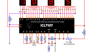
Circuit Diagram of Digital Voltmeter Using Using ICL7107
Schematic Diagram of Digital Voltmeter With LCD Display Using ICL7107 – DIY Project Kit The ICL7107 is a high-precision analog-to-digital converter (ADC) that can be used to build a digital…
Read More » -
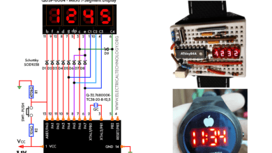
Circuit Diagram of LED Breadboard Wristwatch Using ATtiny84A
How to Make a DIY Breadboard Wristwatch Using ATtiny84A Microcontroller? A breadboard LED wristwatch is an innovative electronic gadget and DIY project for enthusiasts. The watch is based on an…
Read More » -
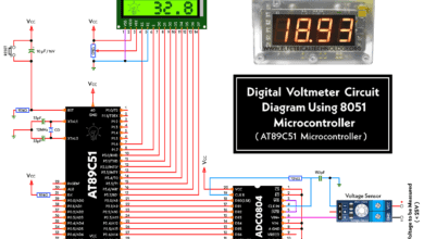
Circuit Diagram of Digital Voltmeter Using 8051 Microcontroller
Schematic Diagram of Digital Voltmeter With LCD Display Using AT89C51 Microcontroller With Source Code A digital voltmeter is an electronic instrument that measures the voltage of an electrical signal. It…
Read More » -
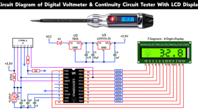
Circuit Diagram of Voltmeter, Continuity & Digital LCD Circuit Tester
Schematic Diagram of Digital Voltmeter & Continuity Circuit Tester With LCD Display Using STM8S003F3 Microcontroller with Firmware You may have come across these simple and small digital voltmeters on the…
Read More » -
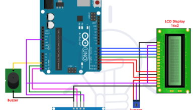
USB Propeller LED Fan Clock – Circuit Diagram & Project Code
USB LED Light Fan Analog Clock Using Arduino NANO – Project Code & Circuit Diagram with Time Setting Feature If you have watched the video of the famous gadget of Mini USB…
Read More » -
Early Flood Detection System Using Arduino – Source Code
Early Flood Monitoring System – Circuit & Project Source Code In both developing and non developing countries, flooding is the massive natural disaster that causes loss of human and animal…
Read More » -
Basic Voltage Doubler Circuit Diagram using 555 Timer IC
How to Make a Basic Voltage Doubler Circuit? As the name of the article suggests, today this article is to help design a circuit which at its output gives a…
Read More » -
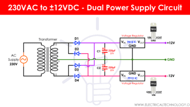
Dual Power Supply Circuit Diagram – 230VAC to ±12VDC
230 VAC to ±12 VDC Dual Power Supply Circuit As the name suggests, this circuit is designed to convert the mains supply voltage of around 220V AC into two voltages…
Read More » -
Simple Cell Phone Charger Circuit Diagram – 5V from 230V AC
How to Make a Simple Cell Phone Charger – Circuit Diagram of 5V DC from 230V AC Have you ever thought about how a cell phone charger works or how…
Read More » -
Push-Pull Amplifier Circuit – Class A, B & AB Amplifier Circuits
Push-Pull Amplifier Circuits using Transistors A Push-Pull transistor circuit is an electronic circuit that uses active devices connected in a particular way that alternatively supply current and absorb from connected load…
Read More »
