How to Wire Double Pole, Double Throw Switch? Wiring DPDT
How to Wire an DPDT Switch? Controlling 120V/240V & 230V Circuit using Double Pole, Double Throw Switches
What is Double Pole, Double Throw (DPDT) Switch?
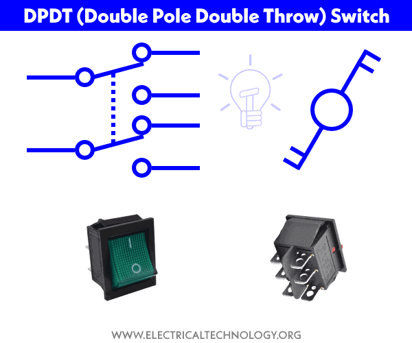
DPDT stands for Double Pole, Double Throw switch. It is basically two SPDT switches packed in a single unit and operated by a single lever (common for both single pole, double throw switches). In short, DPDT (Double Pole, Double Throw) switch is used to control two separate circuit connected to two inputs supply.
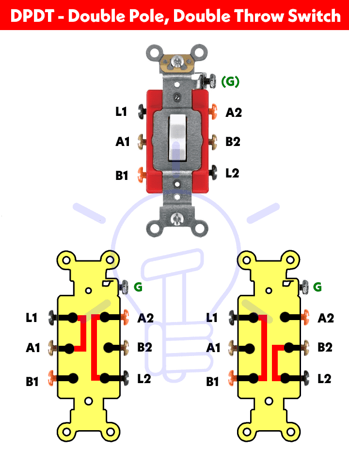
Double Pole, Double Throw switch has 6 terminals as L1, L2, A1, A2, B1 and B2. The L1 and L2 terminals are connected (not always the case) to the incoming lines (say Hot 1 and Hot 2 in case of 240V – NEC or Phase and Neutral in case of 120V or 230V – IEC) and A1, A1, B1 and B2 are connected to the load points according to the design.
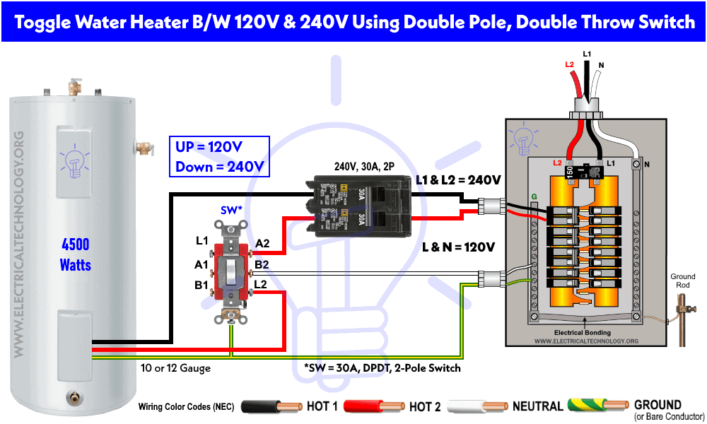
Double Pole, Double Throw (DPDT) switch is used to control two separate appliances connected to the supply for example, a water heater can be toggled between 120V and 240V supply using DPDT switch (wiring diagram is given below), where both supply lines (Hot1 and Hot2 or Line and Neutral) must be switched ON or OFF at the same time for single operation as the action is interchangeable due to the DPDT switch.
Related Wiring Diagrams:
- How to Wire 4-Way Switch (NEC) & Intermediate Switch as 3-Way (IEC)?
- How to Wire Single Pole, Single Throw (SPST) as 2-Way & 1-Way Switch? IEC & NEC
- How to Wire Single Pole, Double Throw (SPDT) as 3-Way & 2-Way Switch? IEC & NEC
Construction & Working of DPDT Switch?
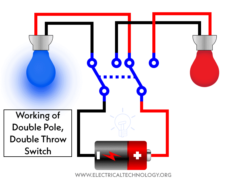
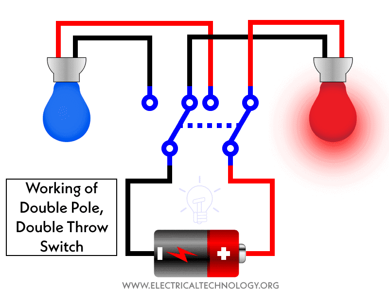
The following gif and short video illustrates how a double pole, double throw switch works in the circuit.
Short Video:
Let’s see how to wire a DPDT switch for different applications.
Controlling & Wiring Two Light Bulbs using DPDT Switch
The following basic wiring diagram shows two colored (Blue and Red) LED bulbs are wired and controlled through a DPDT switch. As shown, the two wires supply (battery or AC source) are connected to the input terminals of double pole, double throw switch terminals (L1 and L2).
The Blue LED bulb is connected through A1 and A2 while the Red color LED light is wired to B1 and B2. At position one (say Up), the Blue light bulb is glowing as the circuit is completed via A1 and A2 and the Red bulb is OFF. At position two (down), the Red light bulb is glowing as the circuit is completed via B1 and B2 and the Red bulb is OFF.
The following gif shows the operation of the above circuit.
Related Posts:
Controlling the Direction of Motor Rotation using DPDT Switch
As shown in the following wiring diagram, the rotation of motor direction is controlled through double pole, double throw switch via phase reversal method.
The two wires supply (as phase, line and neutral) is directly connected to the L1 and L2 terminals of the DPDT switch. The motor is wired to the load terminals of the switch where A1 is connected to B2 and A2 is connected to the B1.
When the switch handle is UP, the motor is rotating in clockwise direction as the circuit is completed through A1 and B2. When the switch lever is down, the motor runs in anticlockwise direction as the circuit is completed through A2 and B1.This way, the rotation of motor direction can be easily changed using DPDT switches.
The following gif shows the operation of the above circuit.
How to Toggle Water Heater between 120V & 240V using DPDT Switch?
A water heater can be toggled between 240V and 120V supply using a double pole, double throw switch. To do this, connect a Hot 1 (black color) from the 2-poles, 30 amp circuit breaker to the water heater element. Now connect Hot 1 (red color) from the breaker to the A2 terminal of the switch and again, connect the L2 terminal to the water heater terminal box.
Click image to enlarge
Now, connect a neutral from the busbar to the B2 terminal of the switch. Finally, connect the ground wire to the water heater. The L1, A1 and B1 terminals screws are unused in this case.
When the switch position is Up, the water heater operates on 240V via Hot 1 and Hot 2. When the switch position is down, the water heater runs on 120V supply via Hot 1 and Neutral.
Keep in mind that you can control any of the two electrical appliances using double pole, double throw switch where one circuit can be operated at the same time while the second one will be OFF.
Related Posts:
Toggle Water Heater between 120V & 240V using DPDT Center-OFF Switch
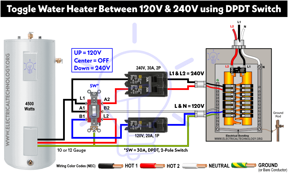
The above wiring diagram only switches the supply between 240V and 120V, to add an additional feature to the circuit e.g. “supply off”, we will use DPDT switch with center-off position. In this case, we will need two breakers viz 30A, 2-Poles, 240V for hot1 and hot 2 and 20A, single pole, 120V for neutral and hot wires.
Just wire the double pole, double throw switch to the water heater as shown in fig below.
Click image to enlarge
The circuit will work as follows.
- Switch lever at Up Position = Water heater operates on 120V supply as the circuit is completed through Line and Neutral (via B1, L1 and B2, L2 terminals).
- Switch handle at Center Position = Switch OFF – No supply to the water heater.
- Switch lever at Down Position = Water heater runs on 240V supply. The circuit is completed through Hot1 and Hot2 (via L1 and L2 are connected (through A1, , A2 and L2 terminals).
Read the Detailed Post about: How to Toggle Electric Water Heater Between 120V and 240V?
Precautions:
Related Electrical Wiring Installations tutorials:
- How to Wire an Outlet Receptacle? Socket Outlet Wiring Diagrams
- How to Find the Number of Outlets on a Single Circuit Breaker?
- How to Find Voltage & Ampere Rating of Switch, Plug, Outlet & Receptacle
- How to Wire a Pilot Light Switch? Wiring of 2 & 3 Way Neon Light Switches
- How to Wire Combo Switch and Outlet? – Switch/Outlet Combo Wiring Diagrams
- How to Wire an AFCI Combo Switch – AFCI Switch Wiring Diagrams
- How to Wire GFCI Combo Switch and Outlet – GFCI Switch/Outlet Wiring Diagrams
- How to Control Water Heater using Switches?
- How to Wire a Ceiling Fan? Dimmer Switch and Remote Control Wiring
- How to Wire Auto & Manual Changeover & Transfer Switch – (1 & 3 Phase)
- Automatic Bathroom Light Switch Circuit Diagram and Operation
- Staircase Wiring Circuit Diagram – How to Control a Lamp from 2 Places by 2-Way Switches?
- How to Control a Lamp by a Single Way or One-Way Switch?
- How to control each lamp by separately switch in parallel lighting circuit?
- How to Control One Light Bulb from Five or Six Different Places using Intermediate Switches?
- Corridor Wiring Circuit Diagram – Hallway Wiring using 2-Way Switches
- Hospital Wiring Circuit for Light Control using Switches
- Hostel Wiring Circuit Diagram and Working
- Godown Wiring Diagram -Tunnel Wiring Circuit and Working
- Tunnel Wiring Circuit Diagram for Light Control using Switches
- How to Wire a UK 3-Pin Plug? Wiring a BS1363 Plug
- How to Wire a UK 3-Pin Socket Outlet? Wiring a BS1363 Socket
- How to Wire a Twin 3-Pin Socket Outlet? Wiring 2-Gang Socket
- How to Wire Combo Switch and Outlet? – Switch/Outlet Combo Wiring Diagrams
- Switch and Push Button Symbols
- Basic Electrical Wiring Diagrams
