Capacitive Sensor and Transducer and Its Applications
What is Capacitive Sensor and its Applications
What is a Capacitor?
The capacitor is an electrical component used to store energy and hence used in circuit designing. They store electrons. Capacitors are also called a condenser. It can be found in a various range of values. A capacitor has two terminals and acts as a passive element.
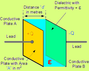
The capacitor has two plates made of conductor with a dielectric medium placed between the plates. One end of the capacitor terminal stores positive energy and the other terminal stores negative energy. Capacitor begins charging when electrical energy is added to it and gets discharged when energy is stopped being sent to the capacitor. So, which means when the capacitor stores current, it is charging and the capacitor starts to discharge when the current discharges. The electrical current stored in the capacitor is expressed in units of Farad.
Capacitor Model
Construction of a Capacitor
Capacitive Transducers:
A capacitive transducer is used for measuring displacement, pressure and many more physical quantities. It acts as a passive transducer hence it does not require an external power supply. As discussed above, a capacitive transducer has two parallel plates with a dielectric medium between the plates. The dielectric medium can be either air, gas or liquid. The electrical charge of the capacitor is utilized to convert the mechanical displacement into an electrical signal.
Principle of Operation:
There will be no charge on either of the plates when the capacitor is being charged. This results in zero electric field intensity between two plates.
Q = CV
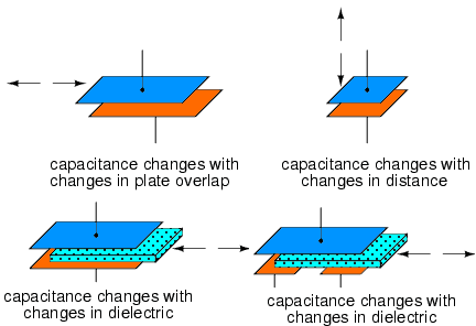
Where C is the proportionality constant, known as the capacitance of the capacitor. The value of C depends on the plate size and dielectric material placed between the plates. It depends on the surface area of the plate, the distance gap between two plates and permittivity of the material. The value of the capacitance is variable in the capacitive transducers. The capacitive transducer is mainly used for measurement of linear displacement. The capacitive transducer uses the following three effects.
- Variation in capacitance of transducer due to changing area of the capacitor plates. → A
- The change in capacitance is because of the change in distances between the plates → d
- The capacitance changes because of dielectric constant. → ε
The capacitance is the proportion of the quantity of power stored on one of the plates to the voltage level across the condenser. The capacity is directly proportional to the plate region and inversely proportional to their range.
ε is the constant of proportionality and it is called as Permittivity of the material that separates the capacitor plates
When the insulating material is used, the capacitance is given as
Where
- ε0 is the permittivity of free space (8.85 x 10⁻¹² F/m)
- εr is the dielectric constant of the insulation medium (εr=1 for air)
- A is the area of the plate (m2 )
- d is the distance between two plates (m)
Related Post: Types of Resistive Sensors – Transducer, Potentiometer & Strain Gauge
Measuring Displacement using Capacitive Sensor
The following methods can be used for measuring displacement using Capacitive Transducer
A Transducer using the change in the Area of Plates

The capacitance of the parallel plates is given as
- Where x is length of capacitor plates
- W = width of the plates
The sensitivity of the displacement is constant, and therefore it gives the linear relation between the capacitance and displacement.
- Related Post: Inductive Sensors – LVDT: Linear Variable Differential Transformer
Capacitive transducer used to measure angular displacement
When the plates are completely overlapped with each other, capacitance will be maximum. 180 degree is the maximum displacement that can be produced by a capacitor. The angular movement changes the capacitance of the transducers. The maximum value of capacitance is expressed as
The capacitance at angle θ is given expressed as,
- θ is the angular displacement in radian
The transducer using the change in distance between the plates
The transducer’s capacitance is inversely proportional to the plate range. The transducer’s one plate is fixed and the other plate is mobile. The displacement to be measured is connected to the mobile plates. The capacitance is inversely proportional to the distance due to the nonlinear response being shown by the capacitor. This sort of transducer is used for tiny displacement measurements
Applications for Capacitive Sensors
Capacitive Humidity Sensor
A sensor of humidity (or hygrometer) senses, measures and records the temperature of humidity and air. The ratio of humidity in the air at a particular air temperature to the highest amount of humidity is called relative humidity. When searching for convenience, relative humidity becomes an significant variable. By putting a thin strip of metal oxide between two electrodes, a capacitive humidity sensor measures relative humidity. The capacitive type sensors are linear and are capable of measuring relative moisture from 0 to 100%.
As the moisture in the atmosphere changes its permittivity, a simple Capacitive RH Sensor can be made from an air-filled capacitor. However, air as a dielectric is not viable for practical applications. Therefore, the space between the condenser plates is generally filled with a suitable dielectric material (isolator), the dielectric constant of which differs when the humidity changes. Using a hygroscopic polymer film as dielectric and depositing two layers of electrodes on either side is the prevalent approach of building a capacitive RH sensor.
Capacitive displacement sensors
Capacitive displacement sensors are used as a reference system for other range sensors for range measurement at low temperature. Other typical applications include mass production tolerance testing, vibration measurement, strain measurement, thickness measurement and thickness control of thin metal foils, thickness measurement of plastic foils during manufacturing, bending of wafers in manufacturing of semiconductors and much more.
Measurement Brake Disc
Vehicle brake disks are subject to very heavy short-term loads. The mechanical abrasion and the growth of extreme heat on the brake disk have a significant impact on the brake disk’s micro-structure. The material used must be able to resist these charges as long as possible without altering its micro-structure. When the load is reapplied, fine cracks lead to a break and endanger the car. Capacitive sensors are used for brake disk deformation measurement. Very few sensors are appropriate for functioning close to the measuring object due to the elevated temperature growth. Capacitive transducers detect nano meter range modifications and evaluate brake wear.
Capacitive transducers – dynamic measurement at turbines or engines
The centrifugal forces exerted on the turbine blades in turbines lead in the blades being expanded. It is essential that no imbalances arise in the design and construction of turbine blades that unbalance the system. Capacitive transducers detect manometer range changes and provide critical information for the evaluation of FEM.
Thickness Measurement
A common application for capacitive detectors is measuring material thickness in a non-contact fashion. A two-channel differential system is the most helpful application in which a distinct sensor is used for each side of the measured piece. Capacitive sensor technology is used for thickness measurement in these applications: Silicon wafer thickness, Brake rotor thickness and Disk drive platter thickness
Assembly Testing
Capacitive sensors are much more sensitive to drivers than non-conductors. Thus, they can be used in finished assemblies to identify the presence / absence of metallic subassemblies. An example is a connector installation that requires an internal metallic snap ring that can not be seen in the final assembly. Online capacitive sensing can detect the faulty portion and signal it from the line to the system.
Advantages & Disadvantages of Capacitive Sensors
Advantages
- For operation, it needs an external force and is therefore very helpful for tiny devices.
- The transducer capacitive is very delicate.
- It provides a good frequency reaction for the dynamic research.
- The transducer has a high impedance of input and therefore has a tiny loading effect.
- It requires very minimal output power
Disadvantages
- The transducer’s metallic components involve isolation.
- The condenser frame needs earthing to reduce the stray magnetic field impact.
- The transducer sometimes displays nonlinear behaviors due to the edge effect regulated by using the guard ring.
- An error is caused by the cable linking across the transducer.
Related Posts:
- Main Difference Between Sensor and Actuator
- Main Difference between Sensor and Transducer
- Automatic Plant Watering & Irrigation System – Circuit, Code & Project Report
- Automated Fingerprint Identification System and How it Works?
- Internet of Things (IOT) and Its Applications in Electrical Power Industry


