DC Circuits MCQs with Explanatory Answers
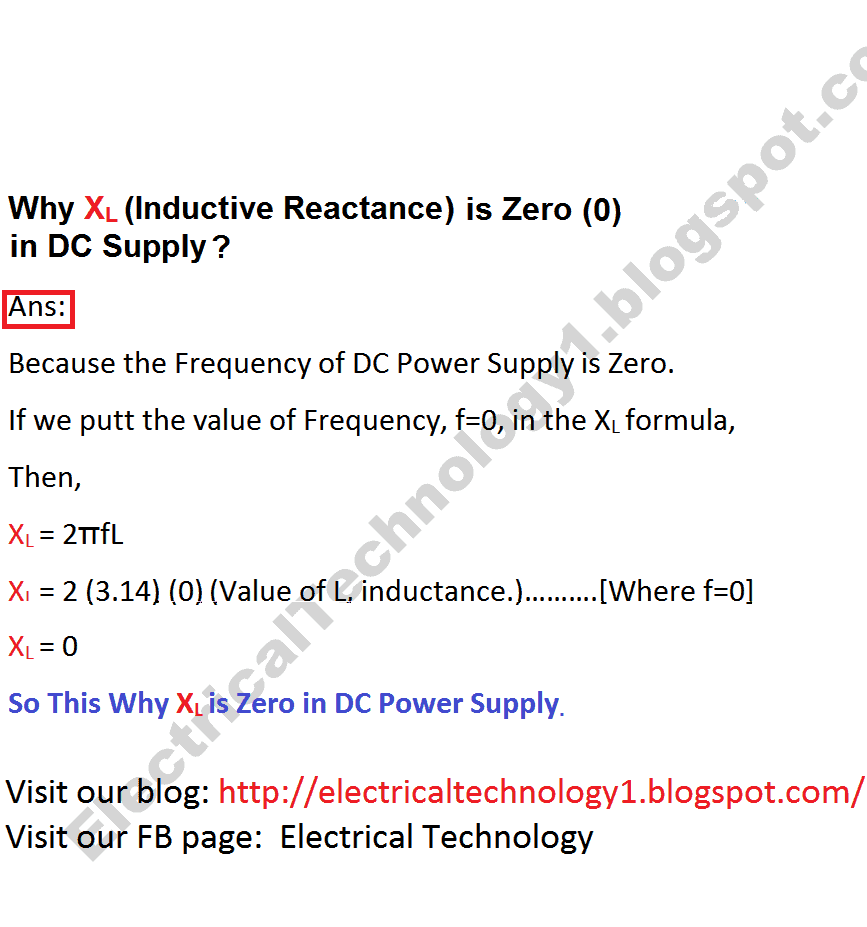
1. In a DC Circuit, Inductive reactance would be_________
- Equal As in AC Circuits
- High
- Extremely High
- Zero
2. In DC Circuits, We can improve the Circuit power factor by Capacitors.
- True
- False
Show Explanatory Answer
Explanation: There is no concept of power factor improvement in DC Circuits because the phase angle (θ) between Current (I) and voltage (V) is 0 and the then power factor becomes Cos θ = 1. So power factor in DC Circuits is 1 and Only 1. In other words there is no reactive component in DC Circuits so the power factor is 1. And the Power Formula in DC Circuits is P = V x I.
3. Kirchhoff’s laws are useful in determining——
- Current flowing in a circuit
- EMFs and Voltage drops in a circuit
- Power in a circuit
- All the above
Show Explanatory Answer
Answer: ( 4 )
Explanation:
For a simple electrical circuit, Ohm’s law can be used to determine the potential difference between two points and current flowing through them. However, for complex electrical network Kirchhoff’s laws are useful.
According to Kirchhoff’s first law, algebraic sum of currents meeting at a junction point is zero.
According to Kirchhoff’s second law, algebraic sum of voltage drops and EMFs in a closed loop or mesh is equal to zero.
Once the value of current or value of voltage drops is determined, it is easy to determine power in the circuit if value of resistance is known.
4. For the circuit given below, current flowing through each branch is——–
- 0.9 Amperes, 0.4 Amperes
- 0.89 Amperes, 0.304 Amperes
- 1 Ampere, 1 Amperes
- 0.60 Amperes, 0.5 Amperes
Show Explanatory Answer
5. Cramer’s rule is used to determine value of circuit parameters using———–
- Linear Equations
- Quadratic Equations
- Parabolic Equations
- None of these
Show Explanatory Answer
Answer: ( 1 )
Cramer’s rule applies use of matrices to solve linear equations comprising of unknown quantities. This is used to find values of unknown electrical parameters in electrical networks where simple methods prove to be inconvenient.
Consider a network system with three linear equations as given below:
Matrix form of the above equation is as given below:
a11 a12 a13
a21 a22 a23
a31 a32 a33
The first step in Cramer’s rule involves determining the determinant of the above matrix, i.e. value of Δ
The next step involves replacing the first column with values of the equations in right hand side and then determining the determinant of the resultant matrix, i.e. value of Δ1
In the same procedure as above, values of Δ2 and Δ3 are determined.
Finally, the unknown values are determined as: x1 = Δ1/Δ; x2 = Δ2/Δ; x3 = Δ3/Δ
6. For the circuit given below, the values of currents I1, I2 and I3 are:
- 2 Amperes, 2 Amperes, -0.8 Amperes
- 3 Amperes, 1 Ampere, 0.5 Amperes
- 3 Amperes, -2 Amperes, -0.6 Amperes
- 5 Amperes, -3 Amperes, -0.8 Amperes
Show Explanatory Answer
Answer: ( 3 )
For loop ABEFA, the linear equation is as given below:
16I1 + 14I2 + 12I3 = 12
Or,
8I1 + 7I2 + 6I3 = 6…………………..1
For loop BCHGB, the linear equation is:
-10 – 12I3 + 2I2 + 2I1 = 0
Or, -6I3 + I2 + I1 = 5 ……………………….2
For loop GHDEG, the linear equation is:
3I3 + 3I2 + 3I1 = 1……………………….3
Matrix for three equations is:
8 7 6 I1 6
1 1 -6 x I2 = 5
3 3 3 I3 1
Determinant for the first matrix is :
Δ = 168 – 147 = 21
Second matrix for the first unknown variable is:
Δ1 = 126 – 147 + 84 = 63
First unknown variable, I1 = Δ1/Δ = 3 Amperes
Third matrix for the second unknown variable is:
8 8 6
1 5 -6
3 1 3
Δ2 = 168 – 126 – 84 = -42
Second unknown variable, I2 = -2 Amperes
8 7 6
Fourth matrix for third unknown variable = 1 1 5
3 3 1
Δ3 = -112 + 98 = -14
Third unknown variable, I3 = -0.6 Amperes
Negative sign shows direction of current is opposite.
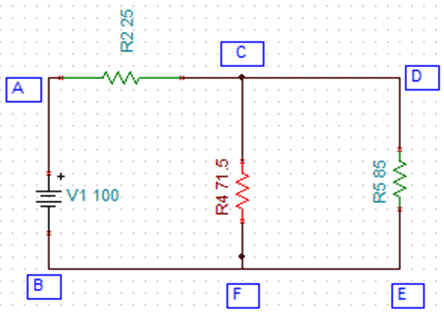
7. For the circuit given below with input of 100 Volts, resistance between terminals A and B and current through the circuit is:
- 56 Ohms, 3 Amperes
- 35.6 Ohms, 2 Amperes
- 63.83 Ohms, 1.56 Amperes
- 39.98 Ohms, 2.4 Amperes
Show Explanatory Answer
Answer: ( 3 )
From the given circuit diagram, it is clear that the resistor network in CEDC is in delta connection as given below:
Transforming above into star connection, we find the values of resistors as given below
From the delta network, sum of individual resistances, Rsum = 200 Ohms
From the star network,
R10 = R4 x R7/200 = 25 Ohms
R9 = R6 x R7/200 = 25 Ohms
R8 = R4 x R6/200 = 12.5 Ohms
Substituting the star connected resistors in the circuit, we get the given circuit as:
Simplifying the circuit will be as given below
Thus total resistance of the circuit, or resistance between points A and B is:
Rt = R2 +(R4IIR5) = R2 + (( R5 x R4 )/( R5 + R4 )) = 63.83 Ohms
Current flowing through the network, I = V/Rt = 100/63.83 Amperes = 1.56 Amperes.
8. For the circuit given below, the current in the branch AB is ———-
- 3 Amperes
- 2 Amperes
- 5 Amperes
- 1 Ampere
Show Explanatory Answer
Answer: ( 2 )
From the given circuit, converting the current source, we get the below equivalent circuit
Applying Superposition theorem:
Step1: Let us consider the voltage source V2 to be short. Hence, equal resistance will be:
R1 = 25 + (30ll40) = 42.14 Ohms
Current through the circuit, I1 = 100/42.14 = 2.373 Amperes
Current through AB, I1’ = I1(40/70) = 1.356 Amperes
Step2: Let us consider the voltage source V1 to be short. Hence, equal resistance will be:
R2 = 40 +(25II30) = 53.63 Ohms
Current through the circuit, I2 = 100/53.63 = 1.864 Amperes
Current through AB, I2’ = I2(25/55) = 0.847 Amperes
Hence, total current through AB = I1’ + I2’ = 2 Amperes ~ 2 Amperes.
9. According to Thevenin’s theorem, any bilateral network can be replaced by a network with——
- An independent current source in parallel to the equivalent resistance
- An independent voltage source in series with the equivalent resistance
- An independent voltage source in parallel to the resistance
- None of these
Show Explanatory Answer
Answer: ( 2 )
According to Thevenin’s theorem, any bilateral network can be represented by a circuit having an independent voltage source in series with a resistance across its terminal. The voltage is termed as Vth or Thevenin voltage and the resistance is Rth or Thevenin resistance.
10. Using Thevenin’s theorem, for the below circuit, current in branch AB is ——
- 0.04 Amperes
- 0.05 Amperes
- 1 Ampere
- 0.07 Amperes
Show Explanatory Answer
Answer: ( 4 )
Considering Thevenin’s theorem if the resistance across terminals AB is removed, the path becomes open circuit.
Hence, current through the circuit = V1/(R1+R5) = 0.33 Amperes
Therefore, voltage across the resistor R5, i.e. Vth = 1.65 Volts
Equivalent resistance, Rth = 8 + (10II5) = 11.33 Ohms
Hence, equivalent Thevenin’s network is:
Current in branch AB = Vth/(Rth+R2) = 0.07 Amperes.
11. Current through the terminals AB, using Norton’s theorem, is ——
- 0.5 Amperes
- 0.46 Amperes
- 1 Amperes
- 0.78 Amperes
Show Explanatory Answer
Answer: ( 2 )
Using Norton’s theorem, let us first remove the resistor R6, between AB such that AB is short circuited.
Now, applying Kirchhoff’s voltage law to the first loop, we get: (Assume I1 is current through R1 and I2 is current through R5 and IN is Norton’s current through AB)
15 – 2I1-4IN = 0
Applying Kirchhoff’s voltage law to the second loop, we get:
8 – 2I2-4IN = 0
Now, from Kirchhoff’s current law at junction A
IN = I1+I2
Hence, both the above loop equations are as given below:
6I1 + 4I2 = 15……….1
2I1 + 3I2 = 4
Solving both the above equations using Cramer’s rule, we get
Negative sign shows I2 is actually in opposite direction
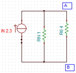
Hence, Norton current, IN = 2.3 Amperes
Now, equivalent resistance, or Norton’s resistance = R1IIR5 = 1 Ohm
Thus, Norton equivalent circuit is as given below:
Current through AB, IAB = IN (RN/(RN+R6)) = 2.3 (1/5) = 0.46 Amperes


 Why Does an Electric Tester Not Work in DC Circuits?
 Why Do The Positive And Negative Wires Spark When Touched?
 What are the Cuts on the Rotor of Motor’s Armature?
 Why Do Wind Turbines Have 3 Blades Instead of 2 or 5?
 Difference Between Edge Triggering and Level Triggering
 Difference between Zener Diode and Avalanche Diode