How to Wire and Install a GFCI Outlet?
What is a GFCI?
GFCI also known as “Ground Fault Circuit Interrupter” is a protective device which automatically detects the ground faults and leakage current and provides personal protection against electrocution. GFCI as an outlet / receptacle, combo or circuit breaker, automatically cuts off the main power supply within millisecond against electric shock.
A GFCI is needed to be installed in moisture, water and water pipes or other similar conditions and locations such as bathroom, kitchen, hot tubes, workshop, swimming pool, laundry, l and any other areas where water and electricity are likely to come in contact. See NEC Code Requirements for GFCI
GFCI devices are especially useful for cord connected appliances and equipment used outdoors or near water. There are multiple types of GFCIs like GFCI outlet, GFCI Combo switch and outlet, GFCI Circuit breaker and portable GFCI.
Related Post: GFCI: Ground Fault Circuit Interrupter. Types, Working & Applications
In today wiring tutorials, we will be showing how to wire and install a GFCI outlet in residential areas to protect the light switch, ordinary outlet / receptacle, light and switches.
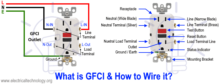
The following figure shows what a GFCI is and how to wire it?
Before installation, it is must to differentiate between a GFCI and ordinary outlet / receptacle. As shown in the above fig, Line (live, hot or phase) terminals are narrow blade while Neutral terminals has wide blades. In a GFCI outlet, there is no break away fin between the upper and lower terminals as like in normal outlet. In normal receptacle / outlet, only one side terminals should be connected to the incoming supply via phase and neutral wires and both outlet will work fine.
In GFCI, the Load and Line Terminals marking should be verified by the nameplate date rating printed on it or by user manual provided by the manufacturer.
In the above diagram, Load is not connected to the GFCI i.e. other outlet, switches and additional load is not protected by the outlet. In simple words, only two outlets in the GFCI are protected. Let’s see how to protect additional loads by GFCI outlet by the following different methods.
Wiring a GFCI Outlet with a Light Switch
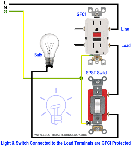
In the first diagram, the single way switch and light bulb is connected to the load terminal of GFCI. This way, the switch and light bulb is GFCI protected.
In the second diagram, the light switch is connected to the line terminals of GFCI. It means, the light switch is not GFCI protected and will operate as a normal circuit.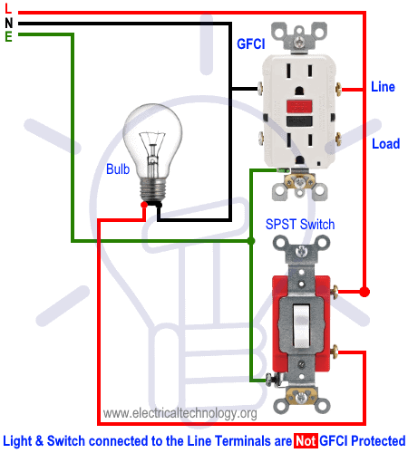
Wiring a GFCI Outlet with a Ordinary Outlet / Receptacle
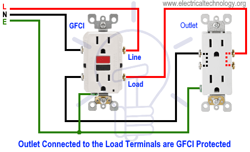
Same like above GFCI wiring diagrams, the ordinary outlet is connected to the load terminals of GFCI. So the GFCI outlet and ordinary outlet connected to the load terminals of GFCI is protected from the ground and earth leakage current.
In the following diagram, the normal outlet is connected to the direct line supply i.e. line terminals of GFCI. This way, the ordinary outlet is not GFCI protected.
- Related Post: How to Wire Combo Switch and Outlet?
Wiring a GFCI Outlet with Combo Switch – Outlet, Receptacle & Light Switch
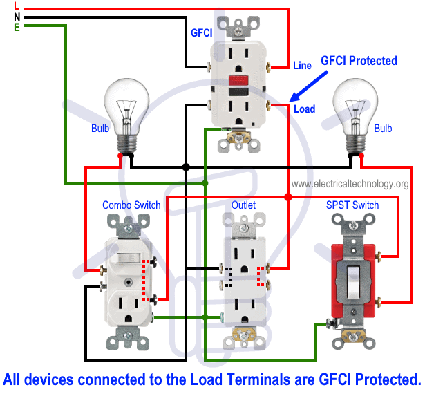
In this GFCI outlet wiring and installation diagram, the combo (switch + outlet), SPST (single way) switch and ordinary outlet is connected to the load side of GFCI. It means, all the connected loads to the load terminals of GFCI are protected. The toggle switch in the combo switch outlet controls the first light bulb while the single way switch controls the second bulb. In short, all the loads is GFCI protected.
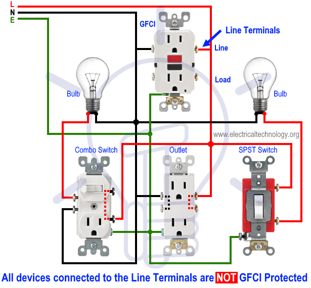
In the following diagram, the above load mentioned before i.e. components and devices are connected to the line terminals of GFCI i.e. they are connected to the direct main supply. This way, the combo switch – outlet, light switch and ordinary outlet are not GFCI protected.
You can add more loads according to your needs but keep in mind that the maximum allowable number of boxed per circuit breaker is 12 where one circuit consists of all boxes on one circuit breaker. In addition, see the following general rules of thumbs and safety precautions for GFCI installation as well.
Rule of Thumbs for GFCI
- Only one GFCI/AFCI per circuit. If you increase the limit, it may leads to trip the circuit.
- GFCI circuit breaker protects the whole circuit while a GFCI outlet can be installed to protect additional outlets and switches etc.
- No need to install an additional GFCI if the circuit is already protected by the GFCI circuit breaker.
- For perfect operation of a GFCI, it is must to properly ground the GFCI or it will not trip instantly but will trip before the serious damage and electric shock.
- No GFCI should be used with some devices like power vented water heater or it will interrupt the proper operation of the circuit.
- Both Test and Reset button on a GFCI is for testing purpose only i.e. GFCI must be tested before final operation to make sure it is working properly.
- Use 14 and 12 gauge wires for 15A and 20A circuit breakers.
- 15A and 20A GFCI can be installed on 15-20A and 20A only (not 15 and 30A) circuit breaker respectively.
Precautions:
- Switch off the main circuit breaker to make sure the power supply is OFF before wiring a GFCI outlet.
- Use the suitable voltage and ampere rating of switch with appropriate wire size and proper size MCB according to the load rating.
- Use the correct polarity i.e. verify the Load and Line terminals while installing a GFCI for protection. In other words, connect the wires to the correct side of outlet for proper operation.
- Regular maintenance, check and test is recommended while test the portable GFCI before each operation.
- Contact the authorized and licensed electrician for GFCI installation if you are not sure about the wiring diagrams.
- The author will not be liable for any losses, injuries, or damages from the display or use of this information or if you try any circuit in wrong format. So please! Be careful because it’s all about electricity and electricity is too dangerous.
Note: We have used Red for Hot, Black for Neutral and Green for Ground for illustration only. Follow your own area wiring color codes according to NEC, IEC etc.
Related Wiring Tutorials:
- Wiring of the Distribution Board with RCD (Residual Current Devices)
- Corridor Wiring Circuit Diagram – Hallway Wiring using 2-Way Switches
- Tunnel Wiring Circuit Diagram for Light Control using Switches
- Hospital Wiring Circuit for Light Control using Switches
- Hotel Wiring Circuit – Bell Indicator Circuit for Hotelling
- Hostel Wiring Circuit Diagram and Working
- Godown Wiring Diagram – Tunnel Wiring Circuit and Working
- Even More Electrical Wiring Installation & Tutorials

 Why Does an Electric Tester Not Work in DC Circuits?
 Why Do The Positive And Negative Wires Spark When Touched?
 Rotor Balancing in the Motors – Types, Methods and Importance
 Difference Between Static Balancing and Dynamic Balancing
 What are the Cuts on the Rotor of Motor’s Armature?
 Why Do Wind Turbines Have 3 Blades Instead of 2 or 5?