Tunnel Wiring Circuit Diagram – Working and Operation
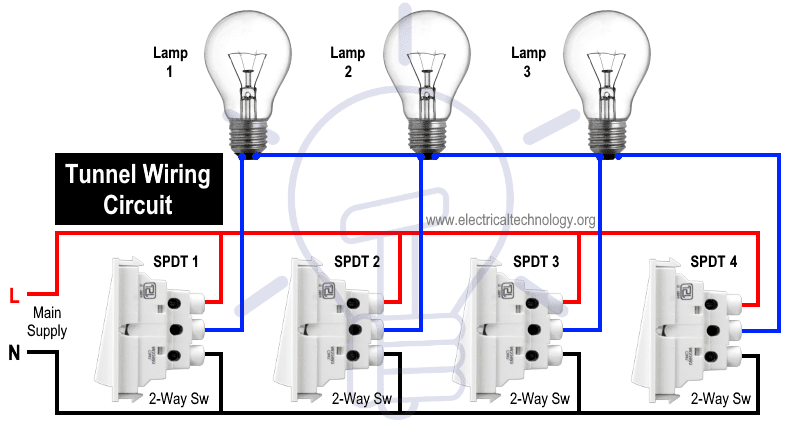
Tunnel wiring circuit is used in open ended corridors and short tunnels like structures. In tunnel wring circuit diagram, we have used SPDT (two-way) switches to control the lighting points in tunnels and corridors. The tunnel circuit control the lamps in four ways as follow.
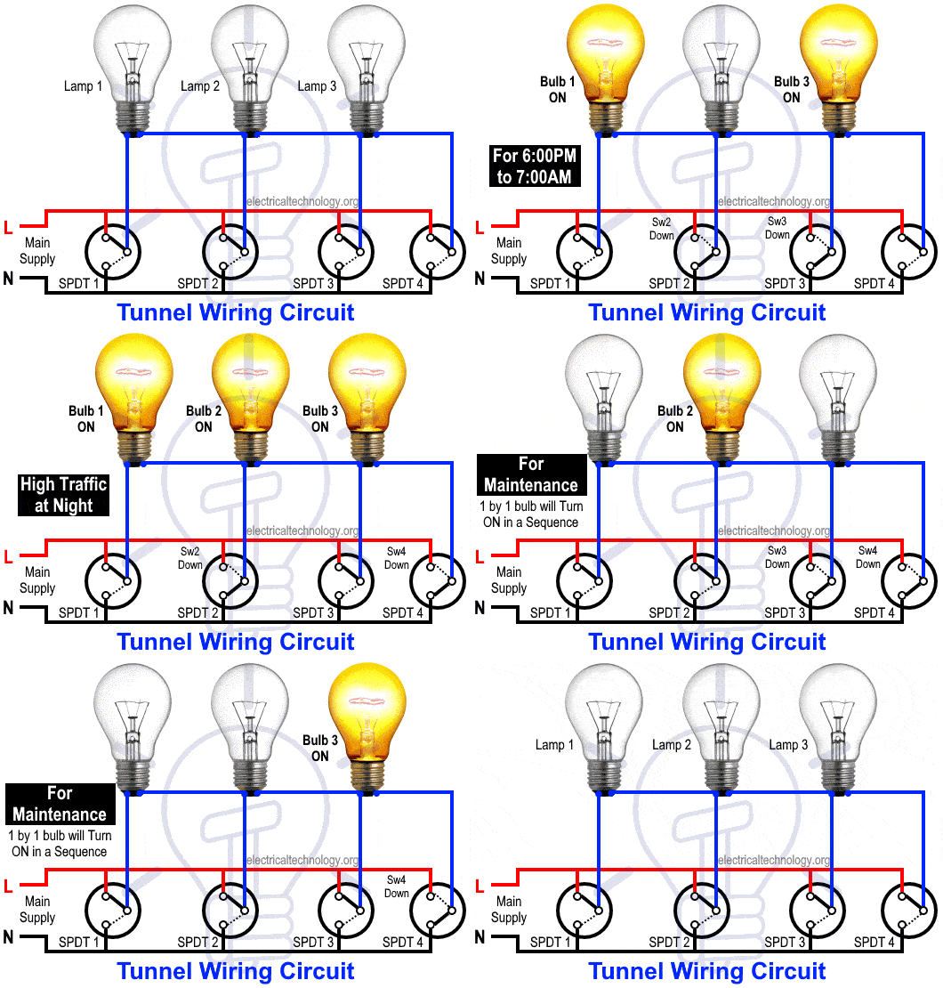
During normal light in the day i.e. from 7AM to 6PM, only the middle one bulb will glow and the first and last one will turned OFF. At night, the first and last one will glow while the middle one will OFF. During high traffic, all the three bulbs will turn ON. During maintenance or special operations, the circuit will work like godown circuit i.e. one by one lamp will turn ON in the sequence.
Keep in mind that the same operation may be achieved by some automation and electronics circuits while we are using only switches for this purpose in the following tutorial.
- Related Wiring Tutorial: Godown Wiring Diagram and Working
Tunnel Wiring Circuit for Light Control
Requirements:
| Component | Rating | Quantity |
| MCB | 120V or 230V, 5A | 1 |
| Two – Way Switch | SPDT, 5A | 4 |
| Light Bulb | 40W | 3 |
| Wire Size | 1.2mm PVC | 2 |
Procedure:
- First of all, turn off the main breaker to make sure the main supply is switched OFF.
- Connect all the switches to the earthing / grounding terminals (not shown in the fig)
- Connect the Neutral wire from MCB directly to the lower terminals of all SPDT (2-way) switches.
- Connect the Live (Phase or Hot) wire from MCB directly to the upper terminals of all SPDT (2-way) switches as shown in the fig.
- Connect all the three bulbs first terminals to the common (middle) terminals of first three SPDT switches.
- Now, connect the first and second bulb 2nd terminal to the second and third bulb first terminals respectively.
- Connect the 3rd bulb second terminal to the common (middle) terminal of 4th SPDT switch.
- Do the proper earthing and grounding according to your local area codes.
- Now turn on the main breaker to make sure the circuit is working properly as planned.
Related Wiring Tutorial: Hotel Wiring Circuit – Bell Indicator Circuit for Hotelling
Working:
The tunnel circuit for lighting control is working in the following sequences:
- During 7:00 AM to 6:00 PM (Day)
First two switches are at down position while the 3rd and 4th are at up position. This way, the middle one i.e. 2nd bulb is turned ON and glowing while the other two bulbs are OFF as normal light do their job at outer and entrance of the short tunnel which leads to save energy.
- During 6:00 PM to 7:00 AM (Night)
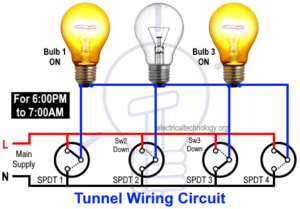
First and last switches are at up while the second and third switches are at down position. This way, the first and last bulbs are turned ON during night and normal traffic.
- During High Traffic at Night
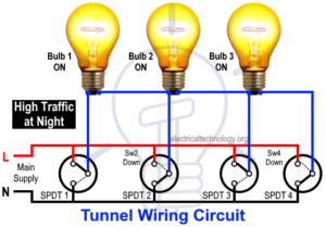
All the bulbs are ON during high traffic at night in the tunnel. The first and third switches are at up and second and fourth switches are down position. This can also be done while switch 1 and 3 at down and switch 2 and 4 at up position i.e. reverse positions of both switches.
- No Operation
All the lamps can be turned off while all the switches are at UP or Down positions.
- During Maintenance
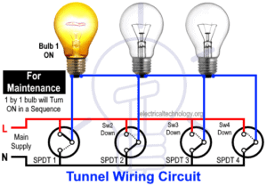
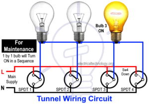
During maintenance operations, the tunnel circuit can be operate like a godown circuit where lamps can be turn ON and OFF in a sequence which is a better option in case of energy conservation.
- Related Wiring Tutorial: Hostel Wiring Circuit Diagram and Working




The following table shows the working of a tunnel wiring circuit.
| SPDT Switches Position | Bulb ONN/OFF |
| S1, S2, S3, S4 = Up | All Bulbs OFF |
| S1, S2, S3, S4 = Down | All Bulbs OFF |
| S1, S2 = Down – S3, S4 = Up | Bulb 2 ON |
| S1, S4 = Up – S2, S3 = Down | Bulb 1 & 3 ON |
| S1, S3 = Up – S2, S4 = Down | All bulbs ON |
| S1, S3 = Down – S2, S4 = Up | All bulbs ON |
| S1 = Up, S2, S3, S4 = Down | Bulb 1 ON |
| S1, S2 = Up – S3, S4 = Down | Bulb 2 ON |
| S1, S2, S3 = Up S4 = Down | Bulb 3 ON |
Keep in mind that two circuits may becomes in series for less than a second while changing the position of switches.
- Related Wiring Tutorial: Hospital Wiring Circuit for Light Control using Switches
If you still unable to get the working of the tunnel circuit wiring, the following animation gif and video shows it perfectly.
Video:
Note: Use the suitable voltage and ampere rating of switch with appropriate wire size and proper size MCB according to the load rating.
Related Post:
- Staircase Wiring Circuit Diagram and Its Working
- How to Control One Lamp From Two or Three Places?
- How to Control a Lamp by a Single Way or One-way Switch?
- How to Control One Light Bulb from Six Different Places?
- What is Intermediate Switch & Its Construction, Working & Uses in Electrical Wiring
- How To Wire Switches In Series?
- How To Wire Switches in Parallel?
- How To wire Lamps in Series?
- How To Wire Lamps in Parallel?
- Which Bulb Glows Brighter When Connected in Series and Parallel & Why?
- Even more Home Electrical Wiring Installation Diagrams & Tutorials

 Why Does an Electric Tester Not Work in DC Circuits?
 Rotor Balancing in the Motors – Types, Methods and Importance
 Difference Between Static Balancing and Dynamic Balancing
 Why Do Wind Turbines Have 3 Blades Instead of 2 or 5?
 How to Calculate the Number of Panels for a Load without Battery Backup?
 Electromagnetic or Electromechanical Relay – Construction, Working, Types, & Applications