Automatic UPS / Inverter Wiring Diagram in Case of some items depends on UPS and the rest on Main or Generator Power
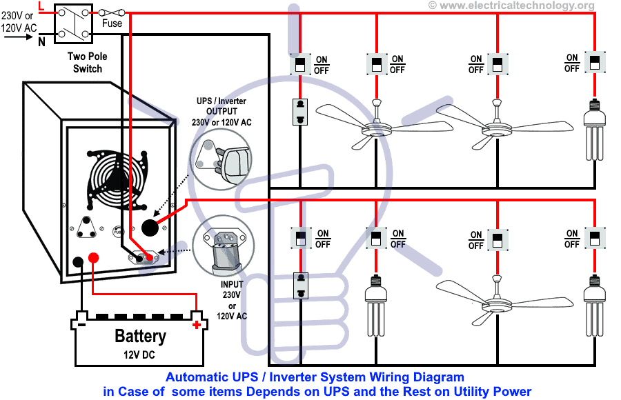
Suppose you have two lighting bulbs, one ceiling fan and a 2-pin socket in the first room and one light bulb, two calling fans and a 2 pin socket in another room. In a second scenario, you are having all the above mentioned electrical appliances in single or different rooms as shown in below fig 1.
- Related Wiring Tutorial: How to Connect Automatic UPS / Inverter to the Home Supply System?
Now, you need to do electrical wiring such a way that two lighting bulbs, a ceiling fan and a 2-pin socket depends on the backup power stored in the batteries connected through UPS / Inverter without interruption (in case of power failure) and the rest on main (utility) power or another power source like generator or wind power. This is the same case where we need a continues power supply to PC and project works without interruption with the help of UPS.
In the following UPS / Inverter wiring diagram, It clearly shows that when the utility power is not available, the connected ceiling fan, two light bulbs and a 2-pin socket will be operated through batteries and UPS as the output Live (Phase) wire of the UPS / Inverter is only connected to them and the rest will be off due to the absence of main power.
When the main utility power restores, all the connected appliances and devices in the home wiring (such as refrigerator, TV, computer, fans, lighting bulbs, washing machines etc) will be working as normal as the main supply is available to all of them. In addition, the main power will also charge the batteries through inverter to charge the batteries as well.
Keep in mind that we only connected the Live (Phase) as output from UPS to some of the appliances where we need continuous power supply because, the Neutral wire is already connected to all of the all sockets and appliances in the home. And yes, You may also use and connect two wires (Neutral & Line) as output from UPS to the electrical appliances as discussed in our earlier UPS / Inverter wiring diagram.
- Related Electrical Wiring Tutorial: UPS / Inverter Wiring Diagram With Auto & Manual Changeover Switch System.
Click image to enlarge

Wiring Color Code:
We have used Red for Live or Phase , Black for Neutral and Green for Earth Wire in single phase. You may use the specific area codes i.e. IEC – International Electrotechnical Commission (UK, EU etc) or NEC (National Electrical Code [US & Canada] where;
NEC:
Single Phase 120V AC:
Black = Phase or Line, White = Neutral and Green/Yellow = Earth Conductor
IEC:
Single Phase 230V AC:
Brown = Phase or Line, Blue = Neutral and Green = Earth Conductor.
Note: Use 6 AWG (7/064″ or 16mm2) cable and wire size to connect the UPS to the main panel board.
General Precautions
- Disconnect the power source before servicing, repairing or installing electrical equipments.
- Use the proper cable in size with this simple calculation method ( How to determine the suitable size of cable for Electrical Wiring Installation)
- Never try to work on electricity without proper guidance and care.
- Work with electricity only in presence of those persons who has good knowledge and practical work and experience who know how to deal with electricity.
- Read all the instructions, user manuals, cautions and follow them strictly.
- Doing your own electrical work is dangerous as well as illegal in some areas.Contact the licensed electrician or the power supply company before practicing any change in electrical wiring connection.
- The author will not be liable for any losses, injuries, or damages from the display or use of this information or if you try any circuit in wrong format. So please! Be careful because it’s all about electricity and electricity is too dangerous.
You may find more related step by step tutorials about UPS / Inverter Wiring Diagrams & Connections with description, and operation. If you are still facing difficulties, please leave a comment in the below comment box.
You may also read other Electrical Wiring Installation Tutorials.
- How to Wire Wire a Distribution Board [Single Phase]?
- How to Wire a Distribution Board with RCD – Single Phase ?
- Single Phase Electrical Wiring Installation in Home – NEC & IEC
- Single Phase Electrical Wiring installation in a Multi-Story Building
 Why Does an Electric Tester Not Work in DC Circuits?
 Rotor Balancing in the Motors – Types, Methods and Importance
 Difference Between Static Balancing and Dynamic Balancing
 Why Do Wind Turbines Have 3 Blades Instead of 2 or 5?
 How to Calculate the Number of Panels for a Load without Battery Backup?
 Electromagnetic or Electromechanical Relay – Construction, Working, Types, & Applications