How to Wire a Light Switch using Single Pole Switch (AKA One Way (IEC) or 2-Way (NEC)?
In today’s basic home electrical wiring installation tutorial, we will show how to wire a single-pole light switch to control a light point using a one-way or single-way switch. The terms “two-way” and “single-pole” are used interchangeably for the same type of switch in the US and Canada.
We will use the basic SPST (Single Pole Single Throw) switch in this tutorial to control the ON and OFF operations of a lamp, bulb or a lighting point from a single location.
We will use the basic SPST (Single Pole Single Throw) switch in this tutorial to control the ON and OFF operations of a lamp, bulb, or lighting point from a single location.
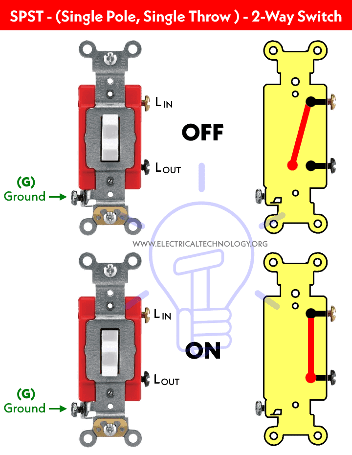
Good to Know: Single Pole, Single Throw (SPST) switch is known as Two-Way switch, toggle switch or Light switch having three terminals (two for lines and one for ground) in North America (US – NEC). While it is known as One-Way or Single-Way switch (having two terminals) in the Europe, UK and IEC following countries.
Before go in details, we have to show the basic construction and operating mechanism of single way switch which is shown in fig below:
Below is a simple step by step tutorial with schematic and wiring diagram which shows how to wire a light switch to control the bulb/lamp from single place with the help of one-way or single way switch?
Related Wiring Diagrams:
- How to Wire 4-Way Switch (NEC) & Intermediate Switch as 3-Way (IEC)?
- How to Wire Single Pole, Single Throw (SPST) as 2-Way & 1-Way Switch? IEC & NEC
- How to Wire Single Pole, Double Throw (SPDT) as 3-Way & 2-Way Switch? IEC & NEC
Controlling a Lamp using Single Way (or 2-Way) Switch
Requirements:
- Single Way Switch (SPST = Single Pole Single Throw) x 1 No
- Lamp (Light Bulb) x 1 No
- Short pieces of cables x 3 No
Procedure:
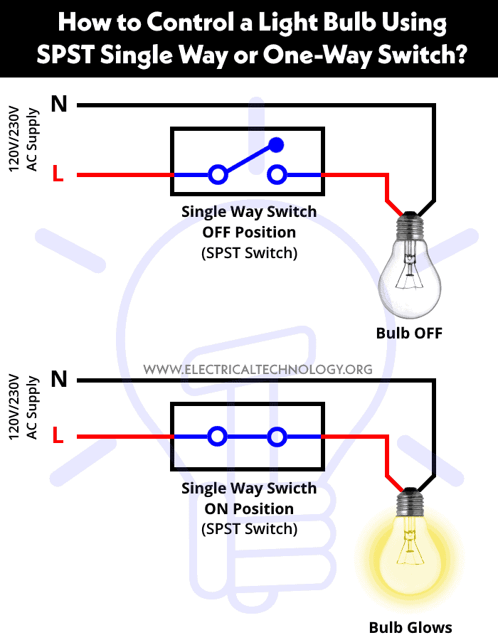
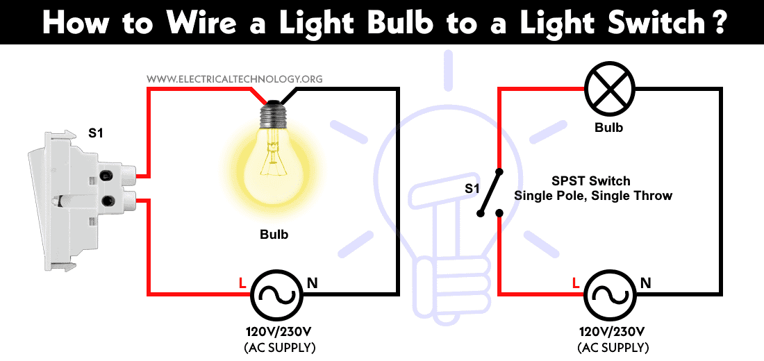
This is just like a series circuit i.e. all the components are connected in series. Just connect the Neutral wire directly to the light bulb and then connect the light bulb to the switch through middle wire. And then connect the live wire to the switch as shown in fig below. Fig given below shows the basic connection of light switch and their position i.e. when the switch is OFF, the circuit acts like an open circuit and the bulb won’t glow. To switch on the bulb, switch S1 must be closed to complete the circuit and glow the light bulb.
In fig below, schematic and wiring diagrams of light switches are shown which shows how to wire a light switch?
Also note that home wire colors may vary according to different areas. In addition, always use and connect the earth wire (direct naked wire to switches, and electrical appliances from earth link in the distribution board to reduce the risk of electric shock and hazard) which is not shown in the figures above.
Related Posts:
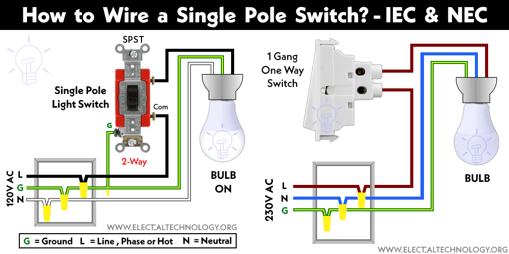
The following wiring diagrams shows how to wire a light bulb to a light switch according to NEC and IEC.
Click image to enlarge
Good to Know:
- Switches and fuses must be connected through Line (Live, Phase or Hot) wire.
- Switches connection in series is not a prefer way to wire home appliances. Parallel or series-parallel wiring method is more reliable.
- Less wires and cables are required in this kind of wiring connection.
Related Posts:
Warning:
- The brass screws should be connected to the Hot (line, live or phase) wire using the IEC & NEC Wire color codes. In case of SPDT and 4-Way (Intermediate switches), black colored screws are used for Hot or common terminals. In short, the color for common terminal is different than other terminals.
- The silver screws should be connected to the Neutral wire (in case of switched outlet)
- The green screw should be connected to the ground / earth wire (Green/Yellow or naked wire)
- If there are no color coded screws on outlets, refer to the user manual or contact a licensed electrician.
- Neutral Wire is not required in 240V outlets wiring (US) Also, Neutral is never connected to the switches.
- Use the suitable voltage and ampere rating of switch with appropriate wire size and proper size MCB according to the load rating.
Precautions:
- Switch off the main circuit breaker to make sure the power supply is OFF before wiring an existing or new outlet or switch with an electrical/junction box.
- Contact the authorized and licensed electrician for switch installation if you are not sure about the wiring diagrams.
- The author will not be liable for any losses, injuries, or damages from the display or use of this information or if you try any circuit in the wrong format. So please! Be careful because it’s all about electricity and electricity is too dangerous.
Related Electrical Wiring Installations tutorials:
- How to Wire an Outlet Receptacle? Socket Outlet Wiring Diagrams
- How to Find the Number of Outlets on a Single Circuit Breaker?
- How to Find Voltage & Ampere Rating of Switch, Plug, Outlet & Receptacle
- How to Wire a Pilot Light Switch? Wiring of 2 & 3 Way Neon Light Switches
- How to Wire Combo Switch and Outlet? – Switch/Outlet Combo Wiring Diagrams
- How to Wire an AFCI Combo Switch – AFCI Switch Wiring Diagrams
- How to Wire GFCI Combo Switch and Outlet – GFCI Switch/Outlet Wiring Diagrams
- How to Control Water Heater using Switches?
- How to Wire a Ceiling Fan? Dimmer Switch and Remote Control Wiring
- How to Wire Auto & Manual Changeover & Transfer Switch – (1 & 3 Phase)
- Automatic Bathroom Light Switch Circuit Diagram and Operation
- Staircase Wiring Circuit Diagram – How to Control a Lamp from 2 Places by 2-Way Switches?
- 2 Way Switch – How to Control One Lamp From Two or Three Places?
- How to Control a Lamp by a Single Way or One-Way Switch?
- How to control each lamp by separately switch in parallel lighting circuit?
- How to Control One Light Bulb from Five or Six Different Places using Intermediate Switches?
- Corridor Wiring Circuit Diagram – Hallway Wiring using 2-Way Switches
- Hospital Wiring Circuit for Light Control using Switches
- Hostel Wiring Circuit Diagram and Working
- Godown Wiring Diagram -Tunnel Wiring Circuit and Working
- Tunnel Wiring Circuit Diagram for Light Control using Switches
- How to Wire a UK 3-Pin Plug? Wiring a BS1363 Plug
- How to Wire a UK 3-Pin Socket Outlet? Wiring a BS1363 Socket
- How to Wire a Twin 3-Pin Socket Outlet? Wiring 2-Gang Socket
- How to Wire Combo Switch and Outlet? – Switch/Outlet Combo Wiring Diagrams
- Switch and Push Button Symbols
- Basic Electrical Wiring Diagrams
 Why Does an Electric Tester Not Work in DC Circuits?
 Why Does the High-Wattage Bulb Glow Brighter in a Parallel Circuit?
 Why Does the High-Wattage Bulb Glow Dimmer in a Series Circuit?
 25 Different Types of Light Switches
 Will I Get an Electric Shock If I Touch the Ground Wire?
 Can the Neutral Wire Cause Electric Shock? Different Cases