Installation of 3-Phase Energy Meter | 3-Φ, 4-Wires Electric Meter 400V & 120V/208V/240V/277V/347/480 & 600V AC Mains Supply & Service
(From the Power Supply to The Main Distribution Board (MDB) & Load Centers according to NEC & IEC)
In the following step by step meter installation tutorials, we will show how to wire a three phase electric meter for 400V AC for 3-Φ & 1-Φ 230V supply (UK, EU based on IEC) and installation of single phase & three-phase 120V, 208V, 240V, 277V and 480V (US based on NEC) regulations for existing or new mains service installation.
For general and clear illustrations, we have used the RED, Yellow & Blue colors for Phase, Line or Live wire while the BLACK color shows the Neutral wire. The color coded versions are also included for both IEC and NEC wiring color coeds.
Click image to enlarge

Warning: These examples show the most commonly used arrangement and generic wiring for electric meter installation in the UK, EU, India, Pakistan, South Africa, United Arab Emirate and other IEC (International Electrotechnical Commission) following countries. The same rule applies for NEC (National Electrical Codes) in the US and Canada. There may be some variations depending on the specific areas, meter designs (smart electronics or electromechanical) and supply systems. The setting may be different in other types of kWh or electric energy meters in different locations around the world. For proper safety. Please contact the supply and service provider to confirm the connection type before electrical wiring installation.
Keep in mind doing your own electrical work is dangerous as well as illegal in some cases. Contact the licensed electrician or the electric power supply provider before practicing any change/modification in electrical wiring connections. In addition, It is must to obtain necessary licenses and approval from the local authority before doing the existing or new service installation.
Be careful: Do not contact metal tools to the screw terminals if the circuit is live especially in case of 230V & 400V Meters (IEC) as the terminal block screws are not insulated.
The author will not be liable for any losses, injuries, or damages from the display or use of this information or if you try any circuit in the wrong format. So please! Be careful because it’s all about electricity and electricity is too dangerous.
Three Phase Meter Wiring for 400V AC – (UK & EU) – IEC
In UK, EU, Asia and IEC following countries, the three phase supply of 400V AC is provided by four wires systems (Three number of Phases (Lines) & Neutral) from the Three Phase 400/230V Transformer to the meter box and further to the main distribution board in the residential buildings.
The good thing is that you can get a 230V single phase supply from a three phase meter load points. All you need is only a one phase wire and a neutral. If you need three-phase 400V, All the three lines and neutral (optional) are needed to run the 3-phase circuits such as 3-Φ, induction motors etc.
It is required now by the Govt of UK to use the smart and digital electric meters instead of analog electromechanical kWh meters.
Good to know: An electric meter is also known as an energy meter, kWh meter or kilo-watt-hour meter which is used to read and record the energy used and power consumption in kilowatt-hours.
Click image to enlarge
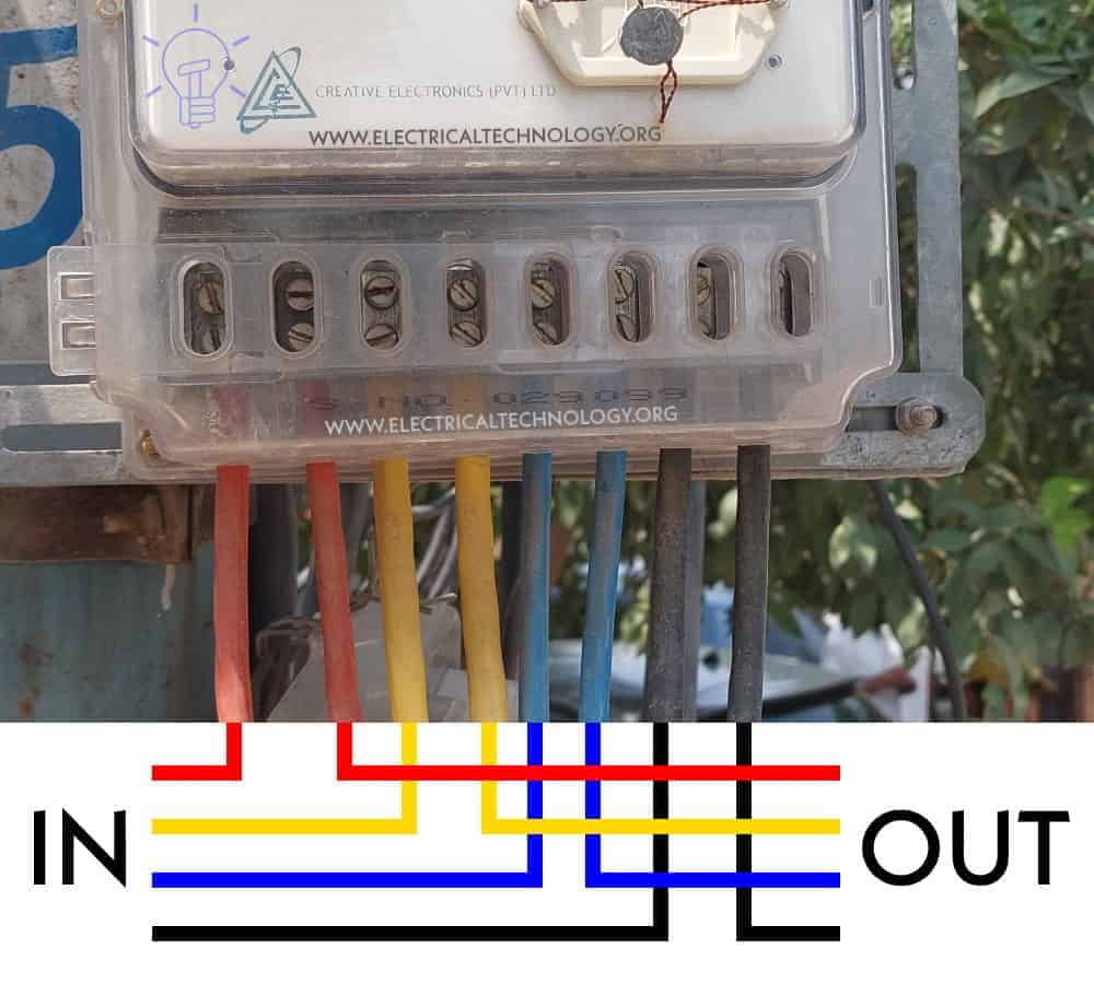
Installation of Three Phase kWh Meter (3-Phase, 4 Wires, 400V AC Energy Meter)
- First of all, make sure to disconnect the main power before working on electrical installations.
- Starting from the left side for MAIN, connect the first incoming (from transformer) Phase (Line) wire to the 1st slot on the meter (Main).
- Connect the second incoming phase wire in the 3rd slot
- Connect the third incoming phase wire in the 5th slot.
- Connect the incoming Neutral (N) wire to the 7th slot on the meter.
- On the Load side, connect the Outgoing Neutral in the 8th slot.
- Now connect the remaining outgoing three phase wires in the 2nd, 4th and 6th slots respectively and connect them to the distribution board as shown in the fig.
Below is the basic connection diagram for installation of a three-Phase, 4-Wires, Wye-400V) kWh meter (Digital or Analog Energy Meter) from the 400VAC supply to the main distribution board in home.
Click image to enlarge
It is suggested to install the meter vertically on its center line. After fitting the screws etc, make sure to close the safety windows. You may turn ON the main power switch after successful insulation of the three phase meter box to check if things are working as expected.
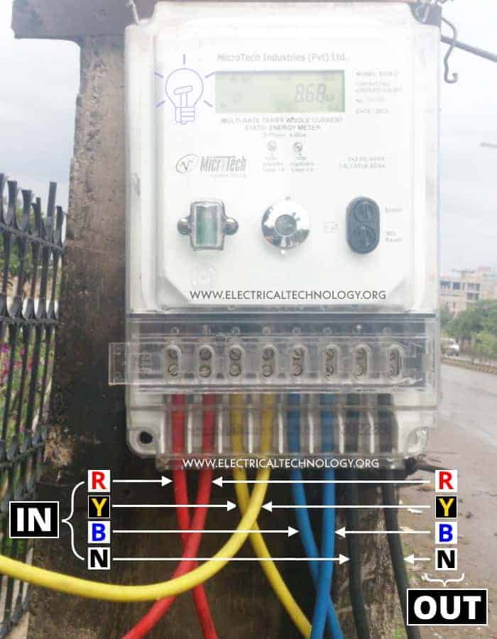
Here is another and real life operational 3-phase energy meter which has been installed on the main utility pole near to the consumer units.
In the above figures and diagrams:
- RIN , YIN & BIN = Incoming Three Phases or Live (Lines) from the 3-phase transformer (Red, Yellow, Blue)
- ROUT , YOUT & BOUT = Outgoing Three Phases or Live (Lines) as a load to the home main distribution board.
- NIN = Incoming Neutral from the transformer.
- NUOT = Outgoing Neutral to the distribution board.
Requirement for 400V, 3-Phase Meter Installation
- You must contact and inform the electricity providers before any kind of service installation/modification or wiring a meter.
- You must use single core PVC & double insulated cables for all phases.
- Use proper marking for all phase cables such as “L1”, “L2”, “L3” and “N” respectively.
- 900mm clearance space in width should be provided in case of electric meters and Low voltage panels and switchgears with a rating of +100 Amps.
- Use minimum of 4mm2 (stranded copper wire) between the consumer unit and electric meter or based on the load ampacity.
- The meter tails (cables used to connect your meter to the cut out o or main breaker) should be double insulated in size of 25mm and properly terminated in to the meter slots.
- The meter tails should be the shortest possible, or at least, the length of meter tails from the cut-out through the metering equipment to the consumer unit) should always be no more than 3 meters of cable (more on BS7671 Reg. 434.2.1).
- You will have to contact a licensed electrician to connect wires from the distribution board to the electric meter. The electricity will be provided later by power service providers by showing them the BS7671 certificate signed by your electrician.
- The meter box must be installed on the external side of the wall which can be easily accessible from the front and unlikely to be damaged.
- There should not be a gas meter, telephone and other utility equipment above or below the electric meter box.
- The meter cabinet (surface mounted or flush mounted) approved by UK power networks can be used based on the proper guidelines and codes.
An 38 mm hockey stick (performed tube) with the meter cabinet must be installed according to the following minimum specifications.
- Meter cabinet from the ground level: 600 mm Min &1100 mm Max
- Meter tails: 25mm
- Clearance from front of cabinet: Min 1000 mm
- Hockey stick (preformed tube): 38 mm ( min 1450mm high & 310mm long) and 500 mm minimum depth in garden.
- Cable access hole: 20/30 mm
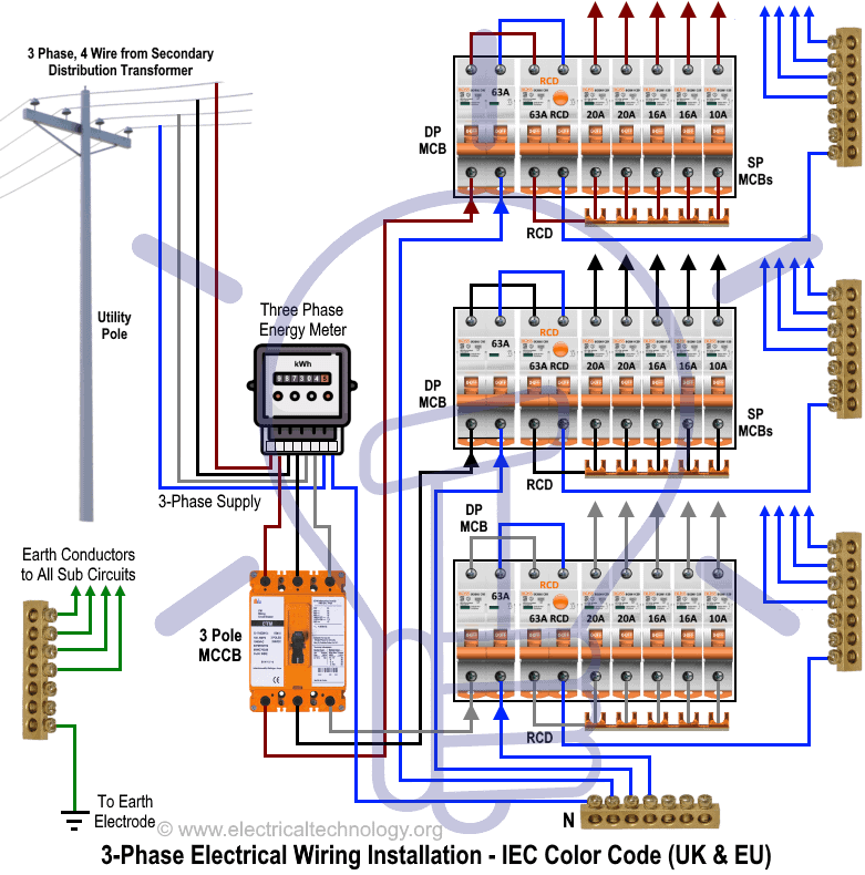
The overall three phase meter wiring (IEC Color Coded) from the utility power supply to the main distribution board will look like this.
Click image to enlarge
Three-Phase Meter Wiring for Different Level of Voltages – US – NEC
The story is totally different in the North America as compared to the UK, EU and the rest of the world. For example, the single phase and three phase voltage levels in the US – NEC are different as compared to the IEC following countries such as the level of common single phase voltages are 120V, 240V. Additionally, both single phase and three phase voltages levels of 120V, 208V, 240V, 277V & 480V are available from the 7200V utility pole mounted transformer.
The level of three phase voltages in the US are as follow:
- 240V, Three Phase, 4 Wires (High Leg Delta) Between Three Hot (Line) wires and Ground.
- 208V, Three Phase, 4 Wires – Between Three Hot (Line) wires and Ground.
- 480V, Three Phase, 4-5 Wires – Between Three Hot (Line) Wires + Neutral and Ground.
- 600V, Three Phase, 4 Wires – Between Three Hot (Line) Wires + Ground.
In the following sections, we will show how to wire an electric meter for 240V, three phase, and 208V three phase & 480V three phase & 600V Three Phase according to NEC.
Click image to enlarge
How to Wire 120V & 208V – (Wye) 1-Φ & 3-Φ Electric Meter?
Let’s see how to wire a 3-phase, 4 wires, 120V & 208V AC energy meter.
- First of all, make sure to disconnect the main power supply before working on electrical installations.
- Connect the three incoming Lines (L1, L2 & L3) from the transformer as “HOT” wire to the top lugs (Black, Red & Blue Colors).
- Connect the three outgoing Lines (L1, L2 & L3) as “HOT” wire (to the load side) from the bottom lugs to the load center or panel box main breaker (Black, Red & Blue Colors).
- You may connect the neutral to the left center lug labeled as (G & N) if needed according to the design. Just connect the load side Lines (Hot wires) and Neutral wires to the main breaker box.
- Connect the ground wire to the small lug (located left to the Line number 3). If there is no Neutral in the terminal box, the ground is still connected to this point.
- You may use minimum #10AWG (Copper) or #8 AWG (Aluminum) for the 120V circuits (see details below).
- #4 AWG (American Wire Gauge) copper wire is suggested for the ground (protective earth) connection.
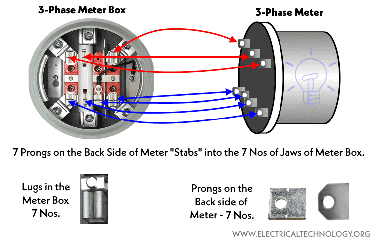
- Now carefully install and fix the meter in the meter box (i.e. 7 meter prongs to 7 jaws in the meter box cabinet).
From this configuration of service lines, the following 1-P & 3-P voltages are available as follow.
Three Phase:
- 208V – Three Phase, 4-Wires (3 Hot Wires + Ground)
Single Phase:
- 208V – Single Phase, 3-Wires (2 Hot Wires + Ground Wires)
- 120V – Single Phase, 3-Wires (2 Hot Wires + Neutral + Ground)
Note: If the Neutral Wire is not available in the meter box, then Only 208V available. If there is Neutral Wires, then both 120V & 208V are available to the panel box i.e.
- Neutral Available: Both 208V & 120V is available
- Neutral Not Available: Only 208V is available
Click image to enlarge
Precaution: If lines are not properly connected to the meter cabinet, or meter prongs are not tightly fixed in the lugs, it will not read the kWh reading and you may not be able to do electric bill calculations based on energy consumption. Additionally the wrong connection of the meter may trip the breaker or may cause a flash, damage to the meter or even serious injury with hazardous fire.
Click image to enlarge
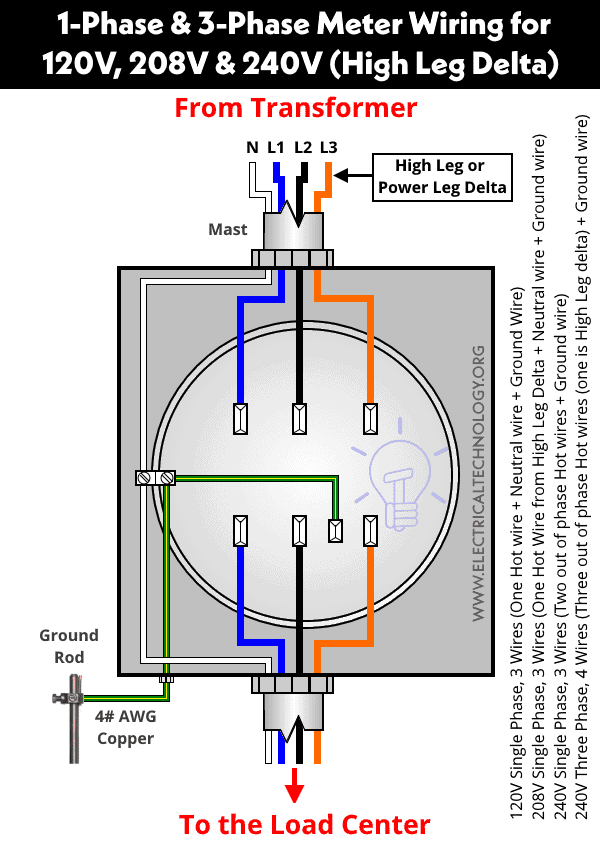
How to Wire 120V, 208V & 240V (High Leg Delta) for 3-Φ & 1-Φ Electric Meter?
Let’s see how to wire a 1-phase & 3-phase, 4 wires or 3 wires, 120V, 208V & 240V AC electricity meter.
- First of all, make sure to disconnect the main power supply before working on electrical installations.
- Connect the three incoming Lines (L1, L2 & L3) from the transformer as “HOT” wire to the top lugs (Blue, Black & Orange Colors). Keep in mind that the 3rd line (as Line 3) on the right in orange color is Power leg (Wild Leg) or High Leg Delta and should be connected to terminals on right of Neutral prong.
- Connect the three outgoing Lines (L1, L2 & L3) as “HOT” wire (to the load side) from the bottom terminals to the load center or panel box main breaker (Blue, Black & Orange).
- You may connect the neutral to the left center terminal labeled as (G & N) as Neutral is available in high leg delta for 208V single phase.
- Now connect the load side Lines (Hot wires) and Neutral wires to the main breaker box.
- Connect the ground wire to the small terminal (located left to the Line number 3). If there is no Neutral in the terminal box, the ground is still connected to this point.
- You may use minimum #10AWG (Copper) or #8 AWG (Aluminum) for the 120V circuits (see details below).
- #4 AWG (American Wire Gauge) copper wire is suggested for the ground (protective earth) connection.
- Now carefully stab and fix the meter with a strong push and restore the power to verify everything is well and working properly. Done.
From this configuration of service lines, the following 1-P & 3-P voltages are available as follow.
Three Phase:
- 240V – Three Phase, 4-Wires (3 Hot Wires (including the High Leg Delta) + Ground)
Single Phase:
- 208V – Single Phase, 3-Wires (1 Hot Wire (Must be High Leg Delta) + Neutral + Ground Wire)
- 240V – Single Phase, 3-Wires (2 Hot Wires + Ground)
- 120V – Single Phase, 3-Wires (1 Hot Wire + Neutral + Ground)
Note: If the Neutral Wire is not available in the meter box, then 208V single phase is not available. If there is a Neutral Wires, then 120V, 208V & 240V are available to the panel box i.e.
- Neutral Available: 208V Single Phase is also Available
- Neutral Not Available: Only 120V & 240V is Available
Click image to enlarge
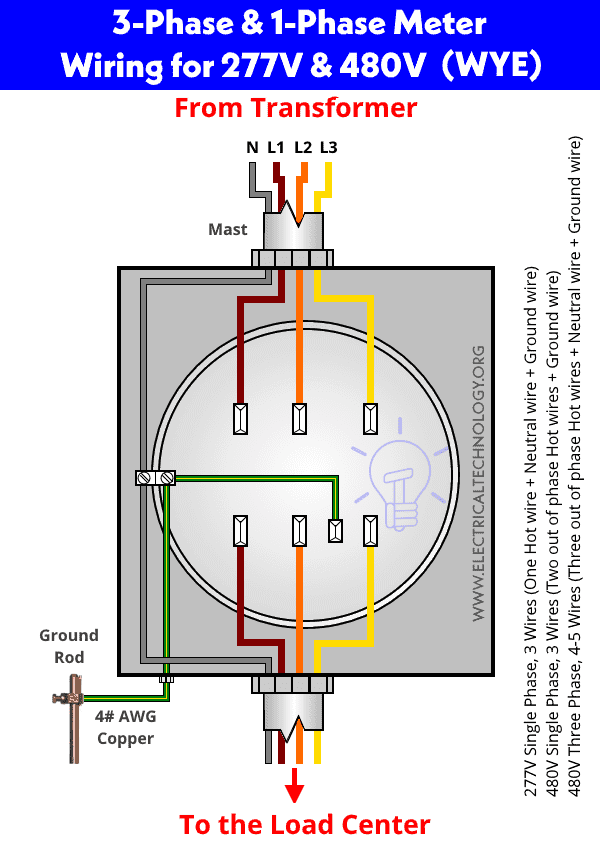
How to Wire 277V & 480V – (Wye) 1-Phase & 3-Phase Meter?
Let’s see how to wire a 1-phase & 3-phase, 5 – wires or 4 wires, 277V & 480V energy meter.
- First of all, make sure to disconnect the main power supply before working on electrical installations.
- Connect the three incoming Lines (L1, L2 & L3) from the transformer as “HOT” wires to the top terminals (Brown, Orange & Yellow Colors).
- Connect the three outgoing Lines (L1, L2 & L3) as “HOT” wire (to the load side) from the bottom terminals to the load center or panel box main breaker (Brown, Orange & Yellow).
- You may connect the neutral to the left center terminal labeled as (G & N).
- Now connect the load side Lines (Hot wires) and Neutral wire in Gray color to the main breaker box.
- Connect the ground wire to the small terminal (located left to the Line number 3). If there is no Neutral in the terminal box, the ground is still connected to this point.
- You may use minimum #10AWG (Copper) or #8 AWG (Aluminum) for the 120V circuits (see details below).
- #4 AWG (American Wire Gauge) copper wire is suggested for the ground (protective earth) connection.
- Now carefully stab and fix the meter with a strong push and restore the power to verify everything is well and working properly. Done.
From this configuration of service lines, the following 1-P & 3-P voltages are available as follow.
Three Phase:
- 480V – Three Phase, 4-5 Wires (3 Hot Wires + Neutral (If needed) + Ground)
Single Phase:
- 480V – Single Phase, 3-Wires (2 Hot Wires + Ground Wire)
- 277V – Single Phase, 3-Wires (1 Hot Wires + Neutral + Ground)
Note: If the Neutral Wire is not available in the meter box, then 277V single phase is not available. If there is a Neutral Wires, then 277V & 480V are available to the panel box i.e.
- Neutral Available: 277V Single Phase is also Available
- Neutral Not Available: Only 480V (1-P & 3-P) is Available
Click image to enlarge
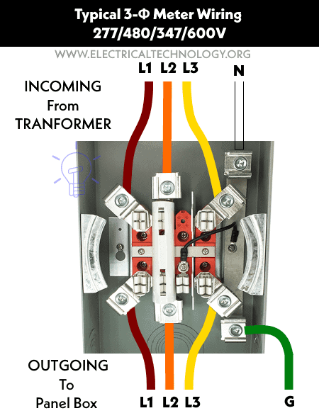
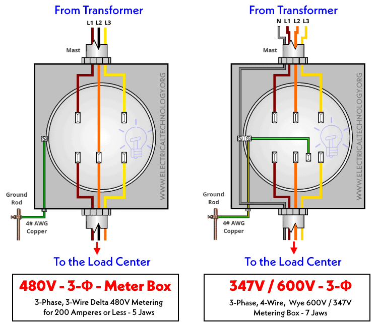
How to Wire 600V / 347V – (Wye) & 480V – Delta 3-Phase Meter?
The following fig shows the wiring for two configurations as follows.
480V Delta Metering (Left Side)
This is only three phase meter wiring i.e. no neutral and single phase system included. There are 5 jaws in the meter cabinet without Neutral but ground is still connected according to the NEC.
347V / 600V – Wye Metering (Right Side)
This meter wiring diagram is the same as for 277V & 480V (1-P & 3-P). There are 7 Jaws i.e. Neutral is included for single phase supply of 347V.
- Three Phase: 600 Volts, 3-Phase across three hot lines + ground wire.
- Single Phase: 347 Volts, 1-Phase across One Hot wire + neutral + ground.
Click image to enlarge
Cable & Wire Sizes For Hot, Neutral & Ground – NEC
- Use a proper wire size based on the load circuits.
- Use #8AWG (Copper) or #6 AWG (Aluminum) for 240V circuits. For 100 Amps, you may
- Use #4 AWG for Copper and #2 AWG Aluminum for service lines (both Hot and Neutral) in case of 100 Amperes.
- For 100 Amps, you may use 2/0 kcmil (AWG) for Copper and 4/0 kcmil for aluminum (based on NEC table 250.122).
- It is required to use a minimum of #4 AWG wire for ground wire to the grounding rod. You may check with local area code for confirmation.
The following table shows the typical wire sizes of Miniman Line conductor, Neutral conductor and Ground wire.
| Breaker size | Typical Wire Sizes For Meter & Panel Box | |||||
| Ⓛ | Ⓝ | Ⓖ | ||||
| Line Conductor | Neutral Conductor* | Ground wire | ||||
| Aluminum | Copper | Aluminum | Copper | Aluminum | Copper | |
| 100 Amp | #2 | #4 | #4 | #4 | #6 | #4 |
| 200 Amp | 4/0 | 2/0 | 2/0 | 1/0 | #2 | #4 |
*Neutral size is determined by load calculation and NEC table 250.122. Always check with your local area codes.
Here is the table in image format if you need to downland as a reference.
General Requirement for 3-Phase Meter Installation
- The meter box must be tightly and securely attached to the wall or firmly fixed to a solid surface at the right level.
- Only use the approved material for the meter box such as conduit and galvanized pipe and attachment brace.
- The wires and lugs connecting screws must be tightened i.e. strong termination.
- Use proper wire size for the exact ampere rating of equipment as well as the amps capacity of panel box and load centers.
- Finally, check and verify the wiring connection according to the user manual guide provided by the supplier with the meter.
Meter box from the ground level: 4ft to 5′-6″.
Clearance from front of meter box cabinet: Min 4ft clear space & 12 inch on all sides.
Separation with Gas & other meters: Minimum 3 to 5ft & 6 inches on the outlet side of gas meter bar.
Underground pipe connection: Minimum 18 Inches below the ground line.
Rigid Conduit: As per NEC
Grounding Wire Size to the Ground Rod: #4 AWG (Copper)
Related Wiring Tutorials about NEC and IEC:
Load Center, Panel & Distribution Boards Wiring Tutorials
NEC – USA
- How to Wire 120V & 240V Main Panel? Breaker Box Installation
- How to Wire 240V, 208V & 120V, 1 & 3-Phase, High Leg Delta Main Panel?
- How to Wire 208V & 120V, 1-Phase & 3-Phase Main Panel? Distribution Board Wiring
- How to Wire 277V & 480V, 1-Phase & 3-Phase, Commercial Main Service Panel?
- How to Determine the Right Size Capacity of a Subpanel?
- How to Wire a Subpanel? Main Lug Installation for 120V/240V
- How to Determine the Number of Circuit Breakers in a Panel Board?
- How to Find the Number of Lights on a Single Circuit Breaker?
- How to Find the Number of Outlets on a Single Circuit Breaker?
- How to Size a Load Center, Panelboards and Distribution Board?
IEC – UK & EU
- How to Wire Single-Phase, 230V Consumer Unit with RCD? IEC, UK & EU
- How to Wire 230V Dual Split Load Consumer Unit? – RCD+MCB
- How to Wire 1-Phase Split Load Consumer Unit? – RCD+RCBO
- How to Wire Combo of 3 & 1-Φ, 400V/230V Distribution Board?
- How to Wire 1-Phase & 3-Phase Split Load Distribution Board?
- How to Wire a Three Phase, 400V Distribution Board? IEC & UK
- How to Wire a Garage Consumer Unit?
- How to Wire a Twin 3-Pin Socket Outlet? Wiring 2-Gang Socket
- How to Wire a UK 3-Pin Plug? Wiring a BS1363 Plug
- How to Wire a UK 3-Pin Socket Outlet? Wiring a BS1363 Socket
- Wiring of the Distribution Board with RCD (Residual Current Devices) – Single Phase Home Supply.
- Wiring of the Distribution Board (Single Phase Supply From Utility Pole & Energy Meter to the Consumer Unit)
General Home Wiring (Both NEC & IEC)
- Single Phase Electrical Wiring Installation in Home according to NEC & IEC
- Three Phase Electrical Wiring Installation in Home
- Single-Phase Electrical Wiring installation in a Multi-Story Building
- Three-Phase Electrical Wiring installation in a Multi-Story Building
- How to Find The Suitable Size of Cable & Wire for Electrical Wiring Installation? Examples in Imperial & Metric System
- How to Find the Proper Size of Circuit Breaker? Breaker Calculator & Examples
- Even More Step by Step Guides and Home Electrical Wiring Tutorials




 Why Does an Electric Tester Not Work in DC Circuits?
 Rotor Balancing in the Motors – Types, Methods and Importance
 Difference Between Static Balancing and Dynamic Balancing
 Why Do Wind Turbines Have 3 Blades Instead of 2 or 5?
 How to Calculate the Number of Panels for a Load without Battery Backup?
 Why Does the High-Wattage Bulb Glow Brighter in a Parallel Circuit?