Active and Passive Frequency Filters – Formulas & Equations
Frequency Filters – Active and Passive Filters Equations and Formulas
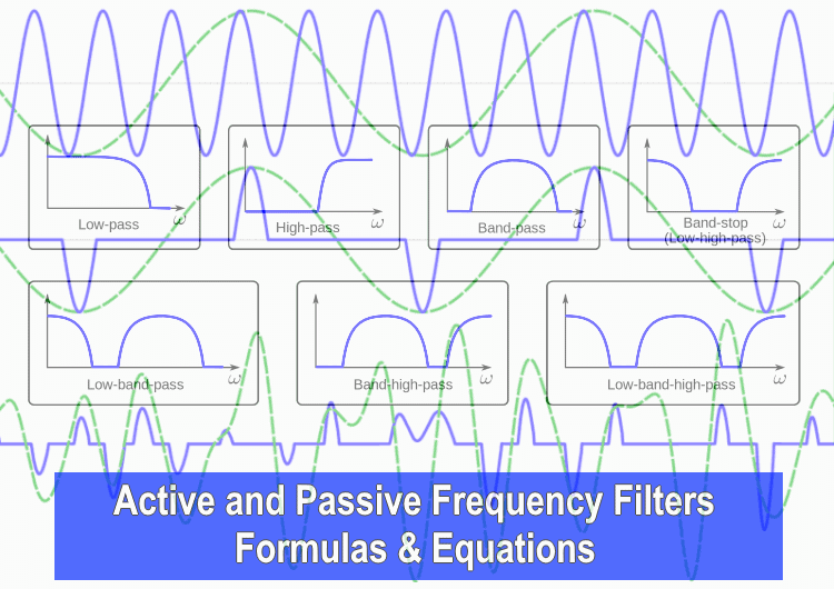
Frequency Filters:
Passive Filters
The type of frequency selecting circuits that are made of only passive components such as resistor, capacitor and inductor.
Low Pass Filter:
It passes low input frequency without any attenuation & blocks high frequency after a fix point known as cutoff frequency.
The output is taken across C & R in RC & RL circuit respectively.
Related Posts:
Cutoff Frequency:
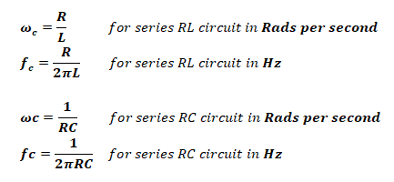
The frequency where the output signal becomes the 70.7% of the input signal is called cutoff, corner or breakpoint frequency, & it is given by;
Transfer Function:
The transfer function for both series RC & RL circuit is same;
Time Constant:
Time constant plays an important role in defining the cutoff frequency of the ciruit.
- τ = 1 / ωc For Both circuit
- τ = L / R For RL circuit
- τ = RC For RC circuit
High Pass Filter:
This type of filter allows high frequency component from its input signal. The circuit used for HPF is same as LPF but the output is taken across R & L in RC & RL circuit respectively.
Related Posts:
Cutoff Frequency:
Same as the Low pass filter.
Only transfer function is changed due to changing the output element.
Time Constant:
It will also remain same.
- τ = 1 / ωc For Both circuit
- τ = L / R For RL circuit
- τ = RC For RC circuit
Band-Pass Filter:
it allows a fixed range of frequency & blocks every other frequency component before or after that allowable region.
Center Frequency:
the center of the allowable band of frequency fc is given by;
Cutoff Frequency:
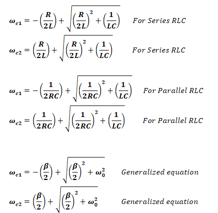
There are two cutoff frequency in band pass filters i.e. Lower cutoff ωc1 & upper cutoff ωc2 , any frequency before ωc1 and after ωc2 is being blocked by the filter.
Bandwidth:
The total range of the allowable frequency is known as bandwidth, from lower cutoff to upper cutoff frequency.
β = ωc2 – ωc1
- β = R/L For Series RLC
- β = 1/RC For Parallel RLC
Quality Factor:
Transfer Function:
Band Reject Filter:
Band reject filter has the same circuit to a band pass filter, except the output is taken across both inductor L and Capacitor C. Thus only the transfer function changes.
Transfer Function:
Related Posts:
Active Filters:
They allow specific frequencies with a gain which can be modified using the resistor network.
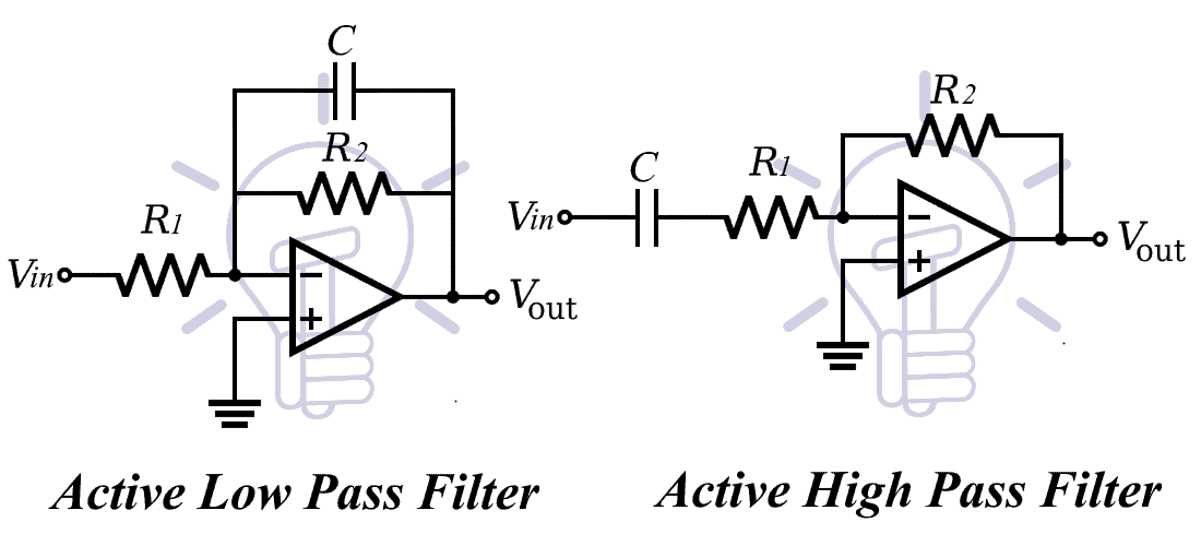
First Order Low Pass & High Pass Filter:
The first order filter contains only one reactive component.
Cutoff Frequency:
The cutoff frequency for both high pass & low pass active filter;
Gain:
Total output voltage gain for this filter is given by;
K = R2 / R1
Transfer Function:
The transfer function for both low pass & high pass active filter with the gain K is given by;
Scaling:
Scaling allow us to use more realistic values of resistors, inductors and capacitors while keeping the quality of the filter. It can be used in passive as well as active filters. There are two types of scaling i.e. magnitude scaling & frequency scaling.
Magnitude Scaling
if you only want to scale the magnitude of the filter.
- R’ = km R
- L’ = km L
- C’ = C / km
Frequency Scaling
When you only want to scale the frequency of the filter
- R’ = R
- L’ = L / kf
- C’ = C / kf
Simultaneous Scaling
When you want to scale the both frequency & magnitude of the filter;
- R’ = km R
- L’ = (km/kf) L
- C’ = (1/kmkf) C
- R’ = scaled resistance
- L’ = scaled inductance
- C’ = scaled capacitance
- km = Magnitude scaling factor
- kf = frequency scaling factor
Related Formulas and Equations Posts:
- Basic Electrical Engineering Formulas and Equations
- Resistance, Capacitance & Inductance in Series-Parallel – Equation & Formulas
- Resistance, Conductance, Impedance and Admittance Formulas
- Basic Electrical Quantities Formulas
- Voltage & Current Divider Rules (VDR & CDR) Equations
- Power Formulas in DC and AC Single-Phase & Three-Phase Circuits
- Magnetic Terms used in Magnetic Circuits – Definition & Formulas
- Time Constant τ “Tau” Formulas for RC, RL & RLC Circuits
- Operational Amplifier (OP-AMP) – Formulas and Equations
- Bipolar Junction Transistor (BJT) – Formulas and Equations
- Diode Formulas & Equations – Zenner, Schockley & Rectifier
- Electric & Magnetic Flux, Density & Field Intensity Formulas
- Formula & Equations for Ohm’s, Kirchhoff’s & Coulomb’s Laws
- Equations & Formulas For RLC Circuits (Series & Parallel)
- Formula and Equations For Inductor and Inductance
- Formula and Equations For Capacitor and Capacitance
- Losses in Electrical Machines – Formulas and Equations
- DC Generator Formulas and Equations
- Power, Voltage and EMF Equation of a DC Motor – Formulas
- Synchronous Generator and Alternator Formulas & Equations
- Synchronous, Stepper and AC Motors Formulas and Equations
- Induction Motor & Linear Induction Motors Formulas & Equations
- Transformer Formulas and Equations
- Electrical & Electronics Engineering Formulas & Equations
- Electrical & Electronics Elements & Symbols


